
Length adjusting device and laser treatment handle

A technology of length adjustment and strength, applied in the field of lasers, can solve the problems of large number of treatment heads, increase of treatment heads, fixed treatment depth, etc., and achieve the effect of ease of use

Pending Publication Date: 2021-12-31
上海瑞柯恩激光技术有限公司
View PDF0 Cites 0 Cited by
  • Summary
  • Abstract
  • Description
  • Claims
  • Application Information

AI Technical Summary

Problems solved by technology

[0005] The disadvantage of the method of replacing treatment heads of different lengths is that the number of treatment heads is large, the replacement is troublesome, easy to lose, and the adjustment range is discontinuous, and there are only several fixed treatment depths corresponding to the treatment heads. If you want to increase the treatment depth, It is necessary to increase the number of treatment heads
The disadvantage of only one length of treatment head is that the treatment depth is fixed, which cannot meet the clinical needs of treating skin lesions with different depths.

Method used


Image

  • Length adjusting device and laser treatment handle
  • Length adjusting device and laser treatment handle
  • Length adjusting device and laser treatment handle

Examples


Embodiment 1

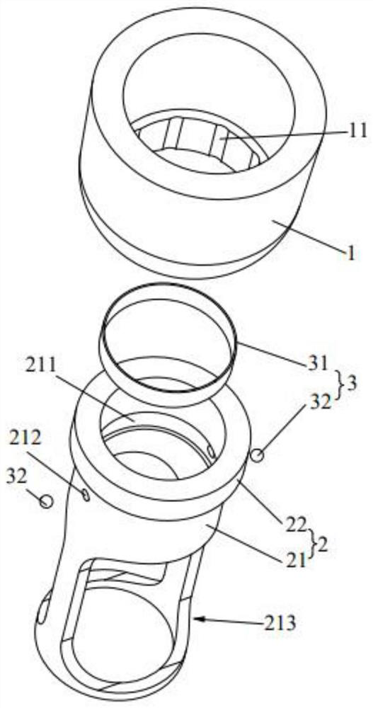
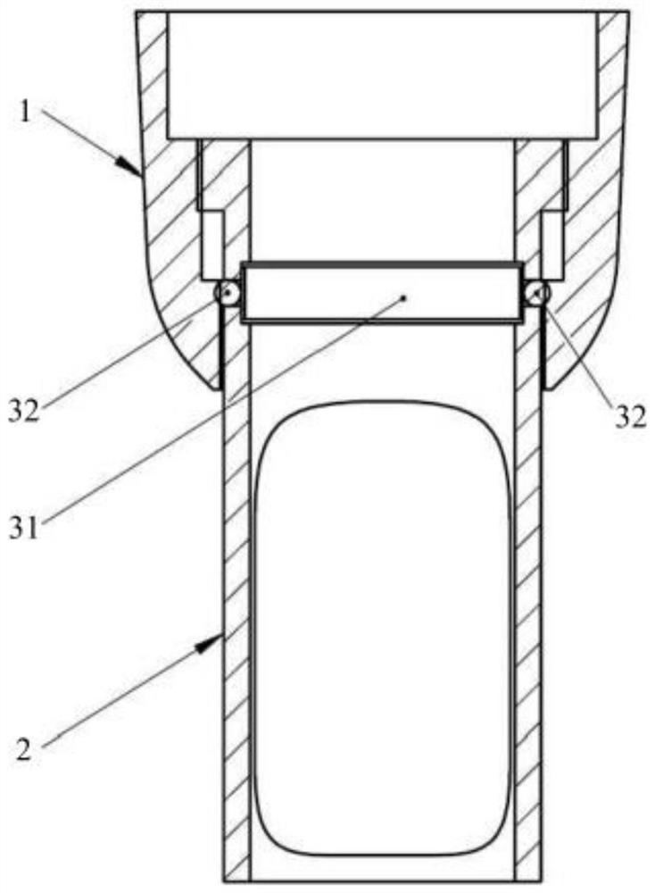
[0038] like Figure 1-3 As shown, this embodiment provides a length adjusting device, which includes a first connecting part 1 and a second connecting part 2 . Among them, the first connecting piece 1 is provided with a first channel; one end of the second connecting piece 2 is passed through the first channel, and the second connecting piece 2 is rotated with a first force, and the first connecting piece 1 and the second connecting piece 2 are opposite to each other. When rotating, the other end of the second connecting piece 2 is away from or close to the first connecting piece 1; among the slot 11 and the snap-in assembly 3, one is set on the first connecting piece 1, and the other is set on the second connecting piece 2 The extension direction of the slot 11 is the same as the extension direction of the first channel; when the snap-in component 3 is snapped into the slot 11, the second connecting piece 2 is rotated with the second force, the first connecting piece 1 and th...

Embodiment 2

[0051] This embodiment also provides a laser therapy handle, including the length adjustment device in the above solution. In this embodiment, the first connecting member 1 may be screwed or clipped to the handle 100 of the laser treatment handle, or integrally formed with the handle 100 of the laser treatment handle.


PUM


Abstract

The invention relates to the technical field of lasers, and particularly discloses a length adjusting device and a laser treatment handle. In the length adjusting device, a first connecting piece is provided with a first channel; one end of the second connecting piece penetrates through the first channel, the second connecting piece is rotated with first force, and when the first connecting piece and the second connecting piece rotate relatively, the other end of the second connecting piece is far away from or close to the first connecting piece; one of the clamping groove and the clamping assembly is arranged on the first connecting piece, and the other one is arranged on the second connecting piece; the extending direction of the clamping groove is the same as that of the first channel; when the clamping assembly is clamped in the clamping groove, the second connecting piece is rotated with second force, the first connecting piece and the second connecting piece can rotate relatively to drive the clamping assembly to be separated from the clamping groove, and the second force is larger than the first force. According to the arrangement, the distance between the other end of the second connecting piece and the first connecting piece can be adjusted, so that the laser focal length can be adjusted, and the treatment head is prevented from being replaced when pathological tissues with different depths are treated.

Description

technical field [0001] The invention relates to the technical field of lasers, in particular to a length adjusting device and a laser treatment handle. Background technique [0002] In the laser beauty industry, laser treatment handles can achieve the purpose of treating patients' tissues, such as honeycomb lattice handles and DOE diffraction handles of picosecond laser treatment equipment. The purpose of this kind of handle is to disperse and focus the large spot parallel beam output by the laser into multiple smaller micro-beams in a lattice. In this way, a smaller wound surface can be treated and the laser energy can be more concentrated. [0003] A treatment head is installed at the end of the laser treatment handle. The end face of the treatment head is also called the treatment surface, which is in direct contact with the patient's skin. Because each micro-beam emitted from the handle is a converging light, the focus position and focal length are fixed, so changing ...

Claims


Application Information

Patent Timeline
IPC IPC(8): A61B18/20
CPCA61B18/20A61B2018/2015A61B2018/0091A61B2018/00053A61B2018/00172
Inventor 刘孝礼雷保军俞仕华
Owner 上海瑞柯恩激光技术有限公司
Learn More