Photovoltaic equipment convenient to clean and working method thereof

A photovoltaic equipment and photovoltaic panel technology, applied in the field of cleaning, can solve the problems of unsuitable photovoltaic equipment cleaning work, blocking sunlight, low work efficiency, etc., and achieve the effect of reducing the workload of workers, reducing labor costs, and simple operation

Active Publication Date: 2021-12-31
徐州市不一科技有限公司
5 Cites 0 Cited by

AI-Extracted Technical Summary

Problems solved by technology

[0003] Since photovoltaic panel components are placed in the open air, that is, placed directly in the sun, after long-term use, especially in some places with relatively harsh environments, there will be a lot of dust and stains on the surface of the photovoltaic equipment, thereby blocking sunlight and affecting power generation ef...

Abstract

The invention discloses photovoltaic equipment convenient to clean and a working method thereof. The photovoltaic equipment comprises a photovoltaic panel assembly and a cleaning structure assembly. The cleaning structure assembly comprises a fixing frame, a moving structure, a water spraying structure and a cleaning structure. The moving structure comprises a first moving wheel structure, a second moving wheel structure, a first end guide wheel structure and a second end guide wheel structure. The whole photovoltaic equipment comprises a plurality of rows of photovoltaic panel assemblies arranged in parallel, the cleaning structure assembly is placed on the photovoltaic panel assemblies needing to be cleaned, and the position is limited through the first end guide wheel structure and the second end guide wheel structure. The first moving wheel structure and the second moving wheel structure drive the cleaning structure assembly to reciprocate along the photovoltaic panel assembly, the two sets of water spraying structures spray cleaning agents and clean water respectively, and the cleaning structure assembly rapidly cleans the surface of the photovoltaic panel assembly. After one row of photovoltaic panel assemblies are cleaned, the cleaning structure assembly is manually placed onto the next row of the photovoltaic panel assemblies for doing cleaning work.

Application Domain

PhotovoltaicsFlexible article cleaning +3

Technology Topic

Structural engineeringManufacturing engineering +5

Image

  • Photovoltaic equipment convenient to clean and working method thereof
  • Photovoltaic equipment convenient to clean and working method thereof
  • Photovoltaic equipment convenient to clean and working method thereof

Examples

  • Experimental program(1)

Example Embodiment

[0039] Embodiment one
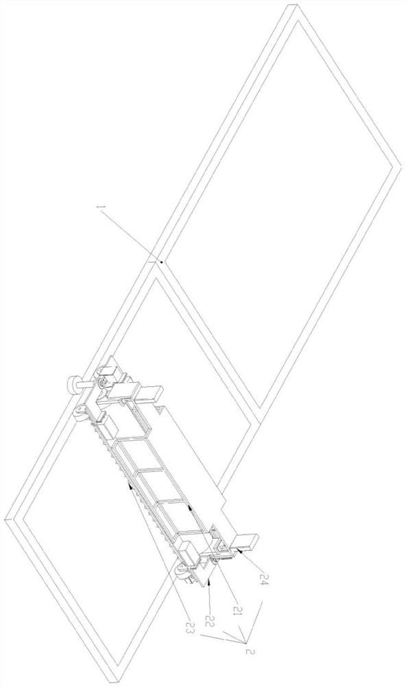
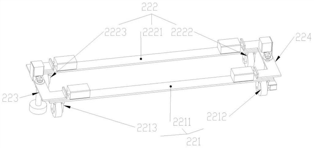
[0040] like figure 1 Shown is a perspective view of the present invention, including a photovoltaic panel assembly 1, a cleaning structure assembly 2, the cleaning structure assembly 2 is arranged on the photovoltaic panel assembly 1; the cleaning structure assembly 2 includes a fixed frame 21, a moving structure 22 , water spray structure 23, cleaning structure 24, such as figure 2 Shown is a perspective view of the moving structure 22, including a first moving wheel structure 221, a second moving wheel structure 222, a first end guide wheel structure 223, and a second end guide wheel structure 224. The first end guide The wheel structure 223 and the second end guide wheel structure 224 are arranged at both ends of the first moving wheel structure 221 and the second moving wheel structure 222; the water spray structure 23 has two groups, which are arranged side by side under the fixed frame 21 and located at Clean both sides of the structure 24 .
[0041] The first moving wheel structure 221 includes a first connecting plate 2211, a driving wheel structure 2212, and a first driven wheel structure 2213, and the driving wheel structure 2212 and the first driven wheel structure 2213 are respectively arranged at both ends of the first connecting plate 2211 ; The second moving wheel structure 222 includes a second connecting plate 2221, a second driven wheel structure 2222, and a third driven wheel structure 2223, and the second driven wheel structure 2222 and the third driven wheel structure 2223 are respectively arranged on the second Connect the two ends of the plate 2221.
[0042] like image 3 Shown is a perspective view of the driving wheel structure 2212, including a first motor 22121, a first coupling 22122, a first shaft 22123, a first bearing seat 22124, a second bearing seat 22125, a first wheel 22126, the first The shaft end of the motor 22121 is connected to one end of the first shaft 22123 through the first coupling 22122, and the first bearing seat 22124, the first wheel 22126, and the second bearing seat 22125 are sequentially arranged on the first shaft 22123; The driven wheel structure 2213, the second driven wheel structure 2222, and the third driven wheel structure 2223 have the same structure, as Figure 4 Shown is a perspective view of the first driven wheel structure 2213, including a second shaft 22131, a third bearing seat 22132, a fourth bearing seat 22133, and a second wheel 22134. The third bearing seat 22132 and the fourth bearing seat 22133 are respectively It is arranged at both ends of the second shaft 22131, and the second wheel 22134 is arranged at the middle position of the second shaft 22131.
[0043] The first end guide wheel structure 223 and the second end guide wheel structure 224 have the same structure, as Figure 5 Shown is a perspective view of the first end guide wheel structure 223 , including a third moving structure 2231 and a guide wheel assembly 2232 , and the guide wheel assembly 2232 is arranged on the third moving structure 2231 .
[0044] The third moving structure 2231 includes a third connecting plate 22311, a first cylinder 22312, a second cylinder 22313, a first guide rail 22314, and a second guide rail 22315, and the plungers of the first cylinder 22312 and the second cylinder 22313 are arranged in parallel The end is connected to the side of the third connecting plate 22311, and the first guide rail 22314 and the second guide rail 22315 are arranged side by side under the third connecting plate 22311; the guide wheel assembly 2232 includes a second motor 22321, a synchronous belt structure 22322, a second Three shafts 22323, the fifth bearing seat 22324, and the third wheel 22325. The shaft end of the second motor 22321 is connected to one end of the third shaft 22323 arranged on the fifth bearing seat 22324 through a synchronous belt structure 22322. The third Wheel 22325 is arranged on the third shaft 22323 other end.
[0045] like Image 6 Shown is a three-dimensional view of the water spray structure 23, including a connecting block 231, a nozzle 232, a first fixing seat 233, and a second fixing seat 234. There are several groups of the nozzles 232 arranged side by side at equal intervals under the connecting block 231. The first fixed seat 233 and the second fixed seat 234 are arranged side by side at both ends of the connecting block 231 and fixed by bolts; the first fixed seat 233 and the second fixed seat 234 have the same structure, as Figure 7 Shown is a perspective view of the first fixing seat 233, on which an arc-shaped slot 2331 is formed.
[0046] like Figure 8 Shown is a perspective view of the cleaning structure 24 , including a fourth moving structure 241 and a cleaning roller structure 242 , and the cleaning roller structure 242 is arranged on the fourth moving structure 241 .
[0047] The fourth moving structure 241 includes a connecting seat 2411, a first moving assembly 2412, and a second moving assembly 2413, and the first moving assembly 2412 and the second moving assembly 2413 are arranged side by side at both ends of the connecting seat 2411; The moving assembly 2412 and the second moving assembly 2413 have the same structure. The first moving assembly 2412 includes a second cylinder 24121, a roller connection block 24122, and a third guide rail 24123. The plunger end of the second cylinder 24121 and the end of the roller connection block 24122 The third guide rail 24123 is arranged on the side of the roller connecting block 24122; the end of the roller connecting block 24122 away from the second cylinder 24121 is also provided with a pressure sensor 244.
[0048] The cleaning roller structure 242 includes a third motor 2421, a second coupling 2422, a fourth shaft 2423, a sixth bearing seat 2424, a seventh bearing seat 2425, and a cleaning wheel 2426. The shaft end of the third motor 2421 passes through the first The second coupling 2422 is connected to the end of the fourth shaft 2423 arranged on the sixth bearing seat 2424 and the seventh bearing seat 2425, and the cleaning wheel 2426 is arranged on the fourth shaft 2423 and is located Between bearing housings 2425.

PUM

no PUM

Description & Claims & Application Information

We can also present the details of the Description, Claims and Application information to help users get a comprehensive understanding of the technical details of the patent, such as background art, summary of invention, brief description of drawings, description of embodiments, and other original content. On the other hand, users can also determine the specific scope of protection of the technology through the list of claims; as well as understand the changes in the life cycle of the technology with the presentation of the patent timeline. Login to view more.

Similar technology patents

Laser radar optical system with optical axis calibrating function and optical axis calibrating method

InactiveCN102353950AOptical axis alignment with high precisioneasy to operate
Owner:INST OF APPLIED ELECTRONICS CHINA ACAD OF ENG PHYSICS +1

Defrosting control method and device

ActiveCN104807132Aeasy to operateDefrost is reasonable
Owner:GREE ELECTRIC APPLIANCES INC OF ZHUHAI

Classification and recommendation of technical efficacy words

  • easy to operate
  • easy to use

Lancet device

InactiveUS7303573B2inexpensively mass-producedeasy to operate
Owner:ABBOTT DIABETES CARE INC

Rapid and non-invasive optical detection of internal bleeding

InactiveUS20050065436A1easy to operaterapid and accurate result
Owner:HO WINSTON ZONH +2

Laser assisted total joint arthroplasty

InactiveUS20090234360A1easy to use
Owner:ALEXANDER VLADIMIR

Enclosure for a portable hemodialysis system

ActiveUS20090114582A1easy to use
Owner:DEKA PROD LLP
Why Eureka
Try Eureka