Composite bending jig and composite bending method for U-shaped structure support

A U-shape and jig technology, applied in the field of stamping parts bending, can solve the problems of U-shape structure strength and stiffness reduction, low production efficiency, U-shape structure uneven thickness, etc., to maintain bending accuracy, realize integration, The effect of reducing the process

Pending Publication Date: 2021-12-31
苏州博晟旺精密机械有限公司
View PDF0 Cites 0 Cited by
  • Summary
  • Abstract
  • Description
  • Claims
  • Application Information

AI Technical Summary

Problems solved by technology

[0003] In the prior art, the U-shaped structure in stamping parts is usually processed by stamping or bending process. Although the stamping process can be quickly formed, there is tension during the stamping forming process, resulting in the thickness of the U-shaped structure. Even, especially the thickness of the curved part and the side wall of the U-shaped structure is thin, and the strength and stiffness of the U-shaped structure are greatly reduced, which cannot meet the force requirem

Method used


Image

  • Composite bending jig and composite bending method for U-shaped structure support
  • Composite bending jig and composite bending method for U-shaped structure support
  • Composite bending jig and composite bending method for U-shaped structure support

Examples


Embodiment Construction

[0044] In order to facilitate the understanding of the present invention, the present invention will be described more fully and in detail below in conjunction with the accompanying drawings and preferred embodiments, but the protection scope of the present invention is not limited to the following specific embodiments. It should be noted that, in the case of no conflict, the embodiments of the present invention and the features in the embodiments can be combined with each other.

[0045] In order to realize the purpose of the present invention, the technical scheme provided by the present invention is:

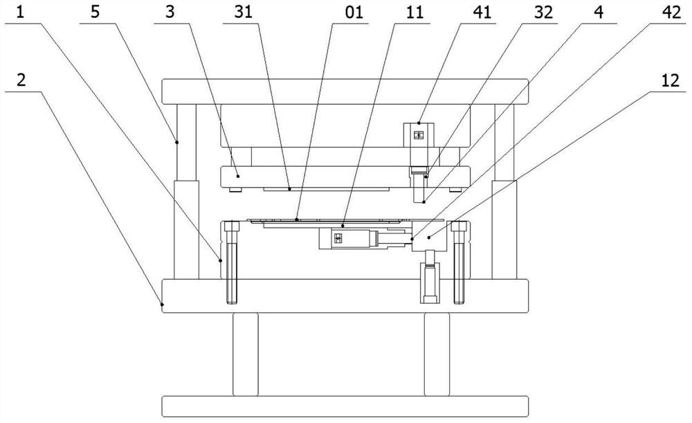
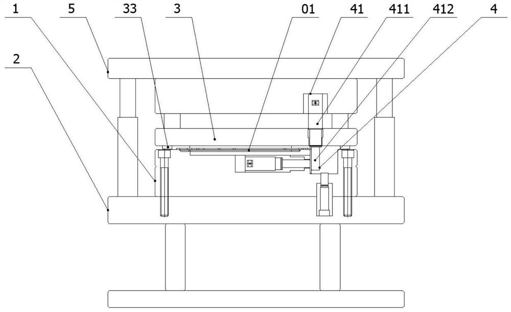
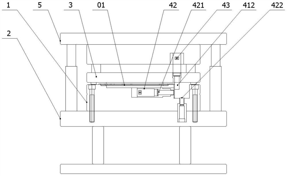
[0046] In some embodiments of the present invention, such as figure 1 As shown, a composite bending fixture for a U-shaped structural support is disclosed, including: a lower template 1, a lower mold support assembly 2, an upper template 3, a composite bending assembly 4 and an upper mold stamping assembly 5; the lower template The upper surface of 1 is provided with a fixed...


PUM


Abstract

The invention discloses a composite bending jig for a U-shaped structure support. The composite bending jig comprises a lower die plate, a lower die supporting assembly, an upper die plate, a composite bending assembly and an upper die stamping assembly, wherein a fixing station and a bending station are arranged on the upper surface of the lower die plate, the lower die supporting assembly is used for bearing a lower die plate, a fixing pressure head and a first bending through hole are arranged on the lower surface of the upper die plate, the fixing pressure head corresponds to a fixing station, the first bending through hole corresponds to the bending station, the composite bending assembly comprises an upper bending assembly and at least one lower bending assembly, the upper bending assembly is used for bending the to-be-bent part of a U-shaped structure support, and the upper die stamping assembly is used for bearing and driving the upper die plate to reciprocate up and down. According to the composite bending jig and the composite bending method, through arrangement of the composite bending assembly, one-time positioning and multi-time bending can be conducted on the U-shaped structure support in one working procedure, so that the bending requirement of the space shape of the U-shaped structure support is met, the working procedure is integrated, the production efficiency is effectively improved, and the production cost is reduced.

Description

technical field [0001] The invention relates to the technical field of stamping parts bending, in particular to a composite bending fixture and a composite bending method for U-shaped structural supports. Background technique [0002] The U-shaped structure of the parts can be processed by different processing methods, such as stamping process manufacturing, bending process manufacturing and casting process manufacturing. For stamping parts, due to their complex structure, thin thickness, and often large batches, The processing technology selection of U-shaped structure will directly affect the efficiency of mass production and the stability of product quality. Therefore, the processing of U-shaped structure of stamping parts is very important for the overall structural forming efficiency of stamping parts. [0003] In the prior art, the U-shaped structure in stamping parts is usually processed by stamping or bending process. Although the stamping process can be quickly form...

Claims


Application Information

Patent Timeline
IPC IPC(8): B21D37/08B21D35/00B21D43/00B21C51/00
CPCB21D37/08B21D35/002B21D43/003B21C51/00
Inventor 贾传明黄鑫
Owner 苏州博晟旺精密机械有限公司
Why Eureka
Try Eureka