Drilling processing equipment for motor fixing seat metal casting after forming

A technology for metal castings and processing equipment, applied in metal processing equipment, drilling/drilling equipment, metal processing machinery parts, etc., can solve the problems of asymmetric threaded holes, cumbersome operation, difficult assembly of motors and fixed motor mounts, etc. , to avoid deviation and reduce vibration

Active Publication Date: 2022-02-18
徐州鸿泰模具制造有限公司
View PDF0 Cites 0 Cited by
  • Summary
  • Abstract
  • Description
  • Claims
  • Application Information

AI Technical Summary

Problems solved by technology

[0003] like Figure 8 The schematic diagram of the structure of the motor fixing seat is shown. The motor fixing seat is mainly formed by casting. Generally, it is necessary to open left and right symmetrical threaded holes on the vertical sections on both sides of the motor fixing seat, so as to be used for the motor and the motor fixing seat. The connection is locked, and the existing motor holder drilling equipment has the following problems in the drilling process: a. To set up a threaded hole on the vertical section of the motor holder needs to be drilled first and then threaded. The drilling method of the motor fixing seat is to clamp and fix the motor fixing seat first, and then use a drilling machine to drill holes on the vertical sections on both sides of the motor fixing seat. In this way, there are vertical sections on both sides of the motor fixing seat. The asymmetrical problem of the threaded holes made it difficult to assemble the motor and fix the motor fixing seat in the future; b. After the drilling machine completes the drilling of the vertical section of the motor fixing seat, it is necessary to remove the motor fixing seat from the clamping mechanism After being disassembled and turned over at a certain angle, the motor fixing seat is clamped and fixed by the clamping mechanism, so that the drilling machine can drill the other part of the vertical section of the motor fixing seat, and the operation is cumbersome

Method used


Image

  • Drilling processing equipment for motor fixing seat metal casting after forming
  • Drilling processing equipment for motor fixing seat metal casting after forming
  • Drilling processing equipment for motor fixing seat metal casting after forming

Examples


Embodiment Construction

[0028] Embodiments of the present invention will be described below with reference to the accompanying drawings; during this process, in order to ensure the clarity and convenience of the description, we may exaggerate the width of the lines or the size of the constituent elements in the illustrations.

[0029] In addition, the following terms are defined based on the functions in the present invention, and may be different according to the operator's intention or practice. Therefore, these terms are defined based on the entire content of this specification.

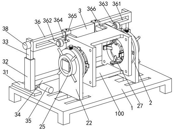
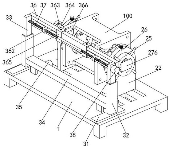
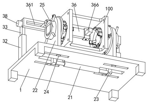
[0030] refer to figure 1 , figure 2 and image 3 , a kind of drilling processing equipment for metal castings of motor holders after forming, including a workbench 1, a clamping device 2 and a drilling device 3, the upper end of the workbench 1 is provided with a clamping device 2 and a drilling device 3, the The drilling device 3 is located behind the clamping device 2 .

[0031] refer to figure 1 , figure 2 a...


PUM


Abstract

The invention relates to the technical field of drilling and processing of motor fixing seats, in particular to a drilling and processing equipment for metal castings of motor fixing seats, which includes a workbench, a clamping device and a drilling device. The upper end of the workbench is provided with a clamping device and drilling device, the drilling device is located behind the clamping device, and the clamping device includes a biaxial hydraulic cylinder, a moving seat, a connecting block, a slider, a rotating ring, a clamping disc and a clamping mechanism; The present invention can realize the drilling of the vertical sections on both sides of the motor fixing seat at the same time, ensuring that the threaded holes on the vertical sections on both sides are located on the same center line. The motor fixing base is driven to rotate synchronously by rotating the clamping mechanism, so that the drilling device can drill holes at other positions in the vertical section of the motor fixing base.

Description

technical field [0001] The invention relates to the technical field of motor fixing seat processing, in particular to a drilling processing equipment for a metal casting of a motor fixing seat after forming. Background technique [0002] The working principle of the motor is to drive the starter rotor to rotate through the energized coil in the magnetic field, and the small gear on the rotor drives the engine flywheel to rotate. The motor needs to be installed and fixed by the motor fixing seat during actual use. [0003] Such as Figure 8 The schematic diagram of the structure of the motor fixing seat is shown. The motor fixing seat is mainly formed by casting. Generally, it is necessary to open left and right symmetrical threaded holes on the vertical sections on both sides of the motor fixing seat, so as to be used for the motor and the motor fixing seat. The connection is locked, and the existing motor holder drilling equipment has the following problems in the drilling ...

Claims


Application Information

Patent Timeline
Patent Type & Authority Patents(China)
IPC IPC(8): B23B41/00B23Q3/06B23Q11/00
CPCB23B41/00B23Q3/06B23Q11/0032
Inventor 蒋黎明
Owner 徐州鸿泰模具制造有限公司
Why Eureka
Try Eureka