Irradiation test tube underwater cutting device

A cutting device and irradiation technology, which is applied in the field of irradiation experiments, can solve the problems of difficult transportation and the inability of large and long irradiation test target components to enter the hot chamber normally, and achieves the effect of reducing research requirements.

Active Publication Date: 2021-12-31
NUCLEAR POWER INSTITUTE OF CHINA
View PDF7 Cites 1 Cited by
  • Summary
  • Abstract
  • Description
  • Claims
  • Application Information

AI Technical Summary

Problems solved by technology

[0005] The technical problem to be solved by the present invention is that the large and long radiation test target assembly cannot enter the hot chamber normally, and the transportation is difficult. Transport issues for target components

Method used


Image

  • Irradiation test tube underwater cutting device
  • Irradiation test tube underwater cutting device

Examples


Embodiment 1

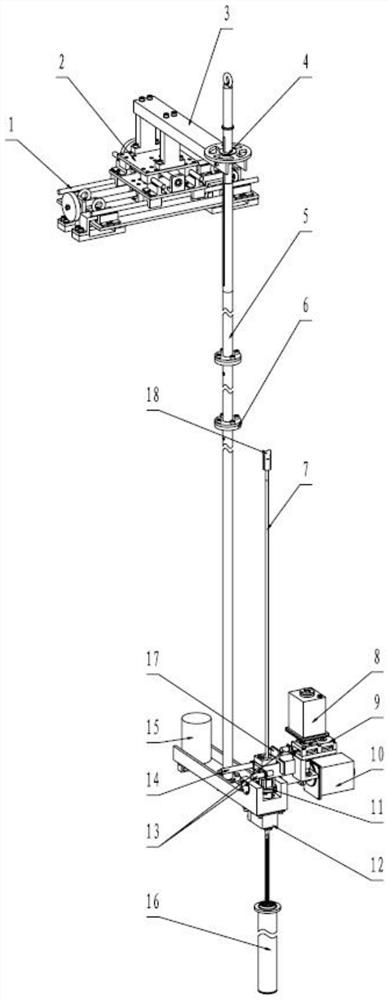
[0072] In view of the above problems, this embodiment provides an underwater cutting device for irradiation test tubes, including a three-dimensional adjustment platform, a coupling rod 5 , a support platform, a cutting assembly and a grabbing assembly 18 .

[0073] The three-dimensional adjustment platform is fixed on the water surface, because the irradiation test tube 7 to be cut needs to be set at 8000mm underwater, and the length of the irradiation test tube 7 to be cut is 4000mm, so the specific length needs to be selected by those skilled in the art , and the corresponding water tank can be set to realize the water surface.

[0074] The connecting rod 5 is vertically arranged, the upper end of the connecting rod 5 is fixedly connected with the three-dimensional adjustment platform, the supporting platform is arranged under the water surface, and the supporting platform is fixedly connected with the lower end of the connecting rod 5;

[0075] The three-dimensional adjust...

Embodiment 2

[0080] This embodiment explains the specific structure of the three-dimensional adjustment platform. For the convenience of description, an XYZ coordinate system is set, that is, a direction located on the horizontal plane is set as the X axis, and a direction located on the horizontal plane and perpendicular to the X axis is set as Y Axis, set the vertical direction and the direction perpendicular to both the X-axis and the Y-axis is the Z-axis;

[0081] The three-dimensional adjustment platform includes an X-axis moving assembly 1 , a Y-axis moving assembly 2 and a Z-axis moving assembly 5 .

[0082] The X-axis moving assembly 1 has a fixed end and a moving end, and the moving end of the X-axis moving assembly 1 moves along the X-axis;

[0083] The Y-axis moving assembly 2 has a fixed end and a moving end, the moving end of the Y-axis moving assembly 2 moves along the Y-axis, and the fixed end of the Y-axis moving assembly 2 is fixedly connected to the moving end of the X-ax...

Embodiment 3

[0102] This embodiment provides a one-circle structure of the connecting rod 5, which is a three-section structure, including an upper segment rod, a middle segment rod and a lower segment rod, generally 8.5m in length.

[0103] The upper segment rod is vertically arranged, and the upper end of the upper segment rod is fixedly connected with the moving end of the Z-axis moving assembly 5;

[0104] The middle rod is vertically arranged, and the upper end of the middle rod is detachably connected with the lower end of the upper rod through the connecting flange 6;

[0105] The lower section bar is vertically arranged, and the upper end of the lower section bar is detachably connected with the lower end of the middle section bar through the connecting flange 6, and the lower end of the lower section bar is fixedly connected with the support platform.

[0106] The upper rod, middle rod and lower rod are detachably connected through the connecting flange 6, so that in the process o...


PUM

PropertyMeasurementUnit
lengthaaaaaaaaaa

Abstract

The invention discloses irradiation test tube underwater cutting device which comprises a three-dimensional adjusting platform, a connecting rod, a supporting platform, a cutting assembly and a grabbing assembly. The three-dimensional adjusting platform is fixedly arranged on the water surface; the upper end of the connecting rod is fixedly connected with the three-dimensional adjusting platform; the supporting platform is fixedly connected with the lower end of the connecting rod; the cutting assembly is fixedly arranged on the supporting platform and is used for cutting a to-be-cut irradiation test tube which is vertically arranged in water; and the grabbing end of the grabbing assembly grabs the to-be-cut irradiation test tube. By means of the irradiation test tube underwater cutting device, the supporting platform is arranged underwater through the connecting rod, the position of the supporting platform relative to the to-be-cut irradiation test tube is accurately adjusted through the three-dimensional adjusting platform, and then underwater cutting is conducted on the large and long to-be-cut irradiation test tube through the cutting assembly.

Description

technical field [0001] The invention relates to the field of irradiation experiments, in particular to an underwater cutting device for irradiation test tubes. Background technique [0002] With the continuous upgrading of nuclear power technology, higher and higher requirements are put forward for the performance of cladding materials for reactor core fuel elements. [0003] At present, the main means of research and development of new cladding materials is to conduct in-core irradiation tests on the target components composed of this material. After the test, they are disassembled and separated into single tubular targets and sent to the hot chamber. After a series of material testing and analysis , and finally evaluate the properties of the material. [0004] The coated material target assembly after the test is a radioactive item, and its transportation and transfer have very strict control requirements. Some large and long radiation test target assemblies are difficult...

Claims


Application Information

Patent Timeline
Patent Type & Authority Applications(China)
IPC IPC(8): B23D79/00B23Q1/25B23Q5/40B23Q7/04B23Q3/00
CPCB23D79/00B23Q1/25B23Q5/40B23Q7/04B23Q3/00B23Q2703/10Y02E30/30
Inventor 王亚军吴瑞张先萌罗文广刘晓松李成业王万金刘洋刘豪邓鹏宇吴旭郑海川
Owner NUCLEAR POWER INSTITUTE OF CHINA
Why Eureka
Try Eureka