Supercharge Your Innovation With Domain-Expert AI Agents!

Direct-acting overflow valve

A technology of direct-acting relief valve and valve body, which is applied in the direction of valve details, safety valves, balance valves, etc., and can solve the problems of poor overflow progress and overflow effect, increased loss of internal components, and shortened service life of the device. , to achieve the effect of improving the overflow progress and poor overflow effect

Active Publication Date: 2021-12-31
YANCHENG JINGGONG VALVE CO LTD
View PDF6 Cites 5 Cited by
  • Summary
  • Abstract
  • Description
  • Claims
  • Application Information

AI Technical Summary

Problems solved by technology

[0004] Aiming at the deficiencies in the prior art, the present invention provides a direct-acting relief valve to solve the problem of increased loss of internal components and the The problem of shortened service life of the device has improved the phenomenon of poor overflow progress and overflow effect. At the same time, the pressure regulating structure can be protected so that the pressure regulating structure is not easy to be corroded, and the stress concentration of the self-locking structure inside the overflow valve is solved. The problem

Method used


Image

  • Direct-acting overflow valve
  • Direct-acting overflow valve
  • Direct-acting overflow valve

Examples


Embodiment Construction

[0022] The following will clearly and completely describe the technical solutions in the embodiments of the present invention with reference to the accompanying drawings in the embodiments of the present invention. Obviously, the described embodiments are only some, not all, embodiments of the present invention. Based on the embodiments of the present invention, all other embodiments obtained by persons of ordinary skill in the art without making creative efforts belong to the protection scope of the present invention.

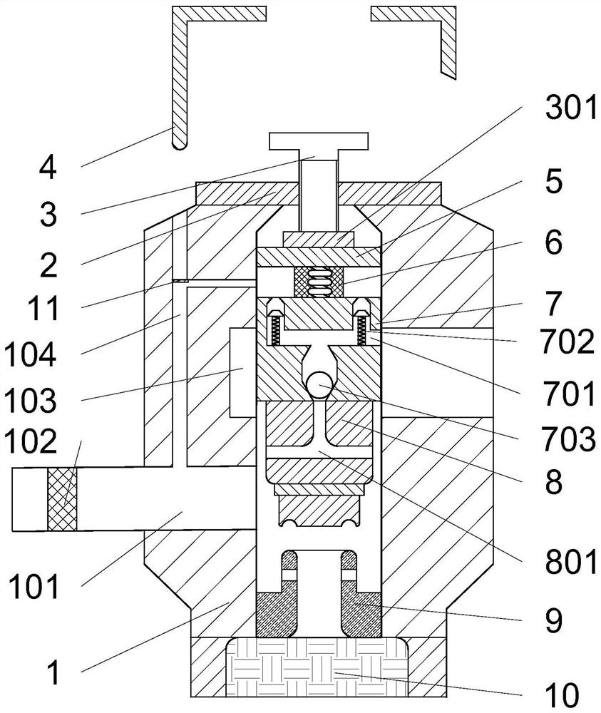
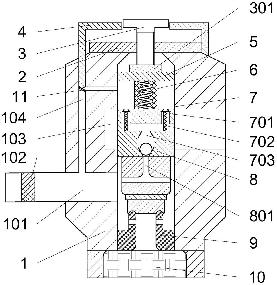
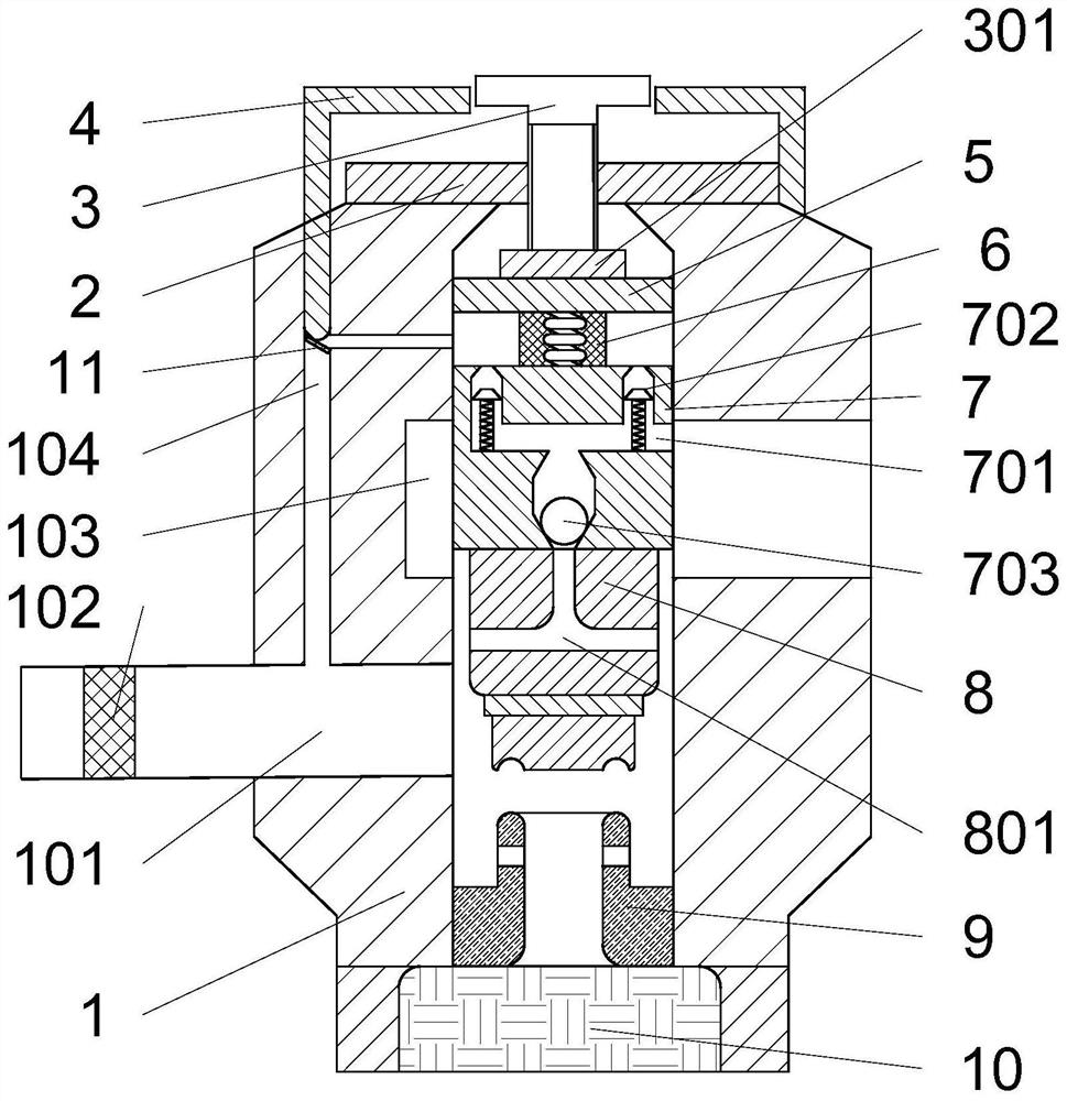
[0023] see Figure 1~3 , a direct-acting relief valve, including a valve body 1, a valve cover 2, an adjustment handle 3, a limit block 5, an elastic column 6, a valve stem assembly 7, a valve core 8, a valve seat 9 and a head 10, the valve The two sides of the body 1 are respectively provided with an oil inlet 101 and an oil outlet 103, the position of the oil inlet 101 is provided with a self-locking chamber 104, and the inside of the valve body 1 is provide...


PUM


Abstract

The invention relates to the technical field of overflow valves, in particular to a direct-acting overflow valve. The direct-acting overflow valve comprises a valve body, a valve cover, an adjusting handle, a limiting block, an elastic column, a valve rod assembly, a valve element, a valve seat and an end socket, an oil inlet and an oil outlet are formed in the two sides of the valve body respectively, a self-locking loop is arranged at the position of the oil inlet, the limiting block, the elastic column, the valve rod assembly, the valve element and the valve seat are sequentially arranged in the interior of the valve body from top to bottom, the two ends of the elastic column are fixedly connected with the limiting block and the valve rod assembly respectively, the limiting block and the valve rod assembly are in sliding fit with the inner wall of a cavity of the valve body, a pressure relief loop is arranged in the interior of the valve rod assembly, a one-way valve is arranged on the upper side of the pressure relief loop and communicates with the self-locking cavity, and a buffering loop is arranged in the interior of the valve element. Through the pressure relief loop, the buffering loop and the elastic column, components in the interior of the valve body can be effectively protected, loss is reduced, a protective cover shell is arranged on the valve cover, a pressure regulating structure is prevented from being corroded and rusted, and therefore the service life of the device is prolonged.

Description

technical field [0001] The invention relates to the technical field of overflow valves, in particular to a direct-acting overflow valve. Background technique [0002] Relief valve is a hydraulic pressure control valve, which mainly plays the role of constant pressure relief, pressure stabilization, system unloading and safety protection in hydraulic equipment. That is to say, in the hydraulic equipment, the pressure of the system is mainly limited by the overflow of the liquid to keep it within the specified pressure, so as to achieve the overpressure protection of the various components of the system. When the hydraulic pressure is lower than the set pressure of the relief valve, the spool is pressed against the oil outlet of the hydraulic oil by the elastic column; when the hydraulic pressure exceeds the set pressure of the relief valve, the oil inlet and the oil outlet are connected to perform overflow discharge pressure. [0003] During the use of the existing direct-a...

Claims


Application Information

Patent Timeline
Patent Type & Authority Applications(China)
IPC IPC(8): F15B13/02F15B21/041F16K17/08F16K17/12F16K47/04F16K47/08
CPCF15B13/024F15B13/022F15B13/027F15B21/008F15B21/041F16K17/06F16K17/08F16K17/048F16K17/044F16K17/12F16K47/04F16K47/08Y02T10/12
Inventor 刘颖陈昊
Owner YANCHENG JINGGONG VALVE CO LTD
Features
  • R&D
  • Intellectual Property
  • Life Sciences
  • Materials
  • Tech Scout
  • Unparalleled Data Quality
  • Higher Quality Content
  • 60% Fewer Hallucinations
Learn More