Anti-fracture dry-type transformer winding structure and using method thereof

A dry-type transformer and winding structure technology, applied in the direction of transformer/inductor coil/winding/connection, etc., can solve the problem of affecting the normal use of dry-type transformers, the inability to automatically adjust the winding position, uneven wiring on the outer wall of the wire formwork, etc. Problems, to achieve the effect of automatically adjusting the winding position, improving the winding density, and not easy to shift the position

Inactive Publication Date: 2021-12-31
连云港天威变压器有限公司
View PDF1 Cites 3 Cited by
  • Summary
  • Abstract
  • Description
  • Claims
  • Application Information

AI Technical Summary

Problems solved by technology

[0006] In order to overcome the above-mentioned defects of the prior art, the present invention provides an anti-breakage dry-type transformer winding structure and its use method, which solves the problem of only being able to prevent the wire from loosening, and cannot automatically adjust the winding during winding. The location makes the wiring on the outer wall of the wire formwork uneven during the winding process, and the wire is easy to shift after winding, which affects the normal use of the dry-type transformer.

Method used


Image

  • Anti-fracture dry-type transformer winding structure and using method thereof
  • Anti-fracture dry-type transformer winding structure and using method thereof
  • Anti-fracture dry-type transformer winding structure and using method thereof

Examples


Embodiment Construction

[0039] The technical solution of this patent will be further described in detail below in conjunction with specific embodiments.

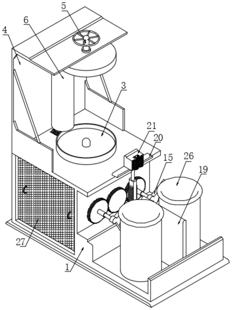
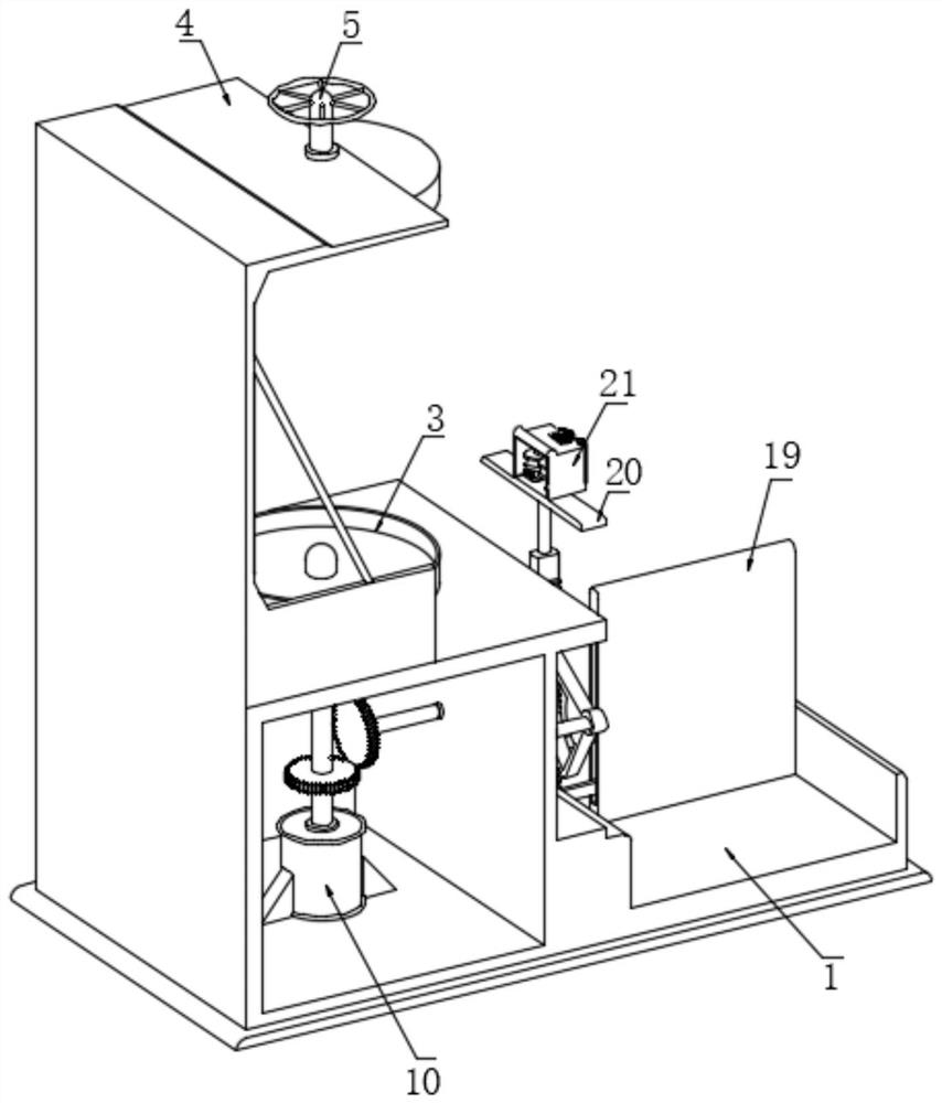
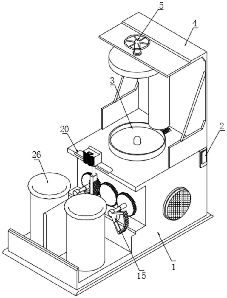
[0040] Such as Figure 1-8 As shown, the present invention provides a technical solution: a breakage-proof dry-type transformer winding structure, including a frame 1, a controller 2 is arranged on the back of the frame 1, the upper surface of the frame 1 and the lower surface of the top plate 4 The surface is fixedly connected, the upper surface of the inner wall of the top plate 4 and the upper surface of the frame 1 are provided with a fixed plate 3, and the left side of the two fixed plates 3 is provided with the same pressure roller 6, and the top and bottom ends of the pressure roller 6 are fixed. The support assembly 8 is connected, and the support assembly 8 is arranged in the chute 7, and the two chute 7 are set on the upper surface of the inner wall of the top plate 4 and the upper surface of the frame 1 respectively, and the lower surfac...


PUM


Abstract

The invention discloses an anti-fracture dry-type transformer winding structure and a using method thereof, which belong to the technical field of dry-type transformers. The anti-fracture dry-type transformer winding structure comprises a rack, a controller is arranged on the back face of the rack, and the upper surface of the rack is fixedly connected with the lower surface of a top plate. According to the structure, the connecting shaft drives the fixing disc to rotate, the fixing disc drives the wire mold frame to rotate, meanwhile, the driving gear drives the driven gear to rotate, and after a single-layer wire is wound on the wire mold frame, the front sector tooth is separated from the toothed bar, and the rear sector tooth is meshed with the toothed bar, and thus, the rear sector teeth can drive the gear rod and the box body to move downward during rotation, in the same way, the box body and the two guide wheels sequentially move up and down in a reciprocating mode, the wire mold frame continuously rotates, compared with a traditional winding mode, the purpose of uniform winding is effectively achieved, the winding position can be automatically adjusted, a wire is not prone to deviating after being wound, the stability is improved, and the normal use of the dry-type transformer is prevented from being influenced.

Description

technical field [0001] The invention belongs to the technical field of dry-type transformers, in particular to a breakage-proof dry-type transformer winding structure and a use method thereof. Background technique [0002] A power transformer is a static electrical device that is used to change an AC voltage (current) of a certain value into another voltage (current) with the same frequency or several different values. The transformer is used to convert AC A static electrical device that transmits alternating current energy through voltage and current. It realizes electric energy transfer based on the principle of electromagnetic induction. Transformers can be divided into power transformers, test transformers, instrument transformers and special-purpose transformers in terms of their uses. [0003] Dry-type transformers are widely used in local lighting, high-rise buildings, airports, wharf CNC mechanical equipment and other places. Simply put, dry-type transformers refer ...

Claims


Application Information

Patent Timeline
Patent Type & Authority Applications(China)
IPC IPC(8): H01F27/30H01F27/28
CPCH01F27/30H01F27/28
Inventor 宋丽赵伟伟
Owner 连云港天威变压器有限公司
Why Eureka
Try Eureka