Pole piece, roll core and battery

A pole piece and winding core technology, applied in the field of batteries, can solve the problems that cannot meet the needs of high current and high voltage occasions

Active Publication Date: 2021-12-31
三一技术装备有限公司
View PDF12 Cites 1 Cited by
  • Summary
  • Abstract
  • Description
  • Claims
  • Application Information

AI Technical Summary

Problems solved by technology

[0003] Therefore, the technical problem to be solved by the present invention is to overcome the defect that the batteries formed by the pole pieces in the prior art cannot meet the needs of high-current occasions or high-voltage occasions when the battery power is constant.

Method used


Image

  • Pole piece, roll core and battery
  • Pole piece, roll core and battery
  • Pole piece, roll core and battery

Examples


Embodiment approach

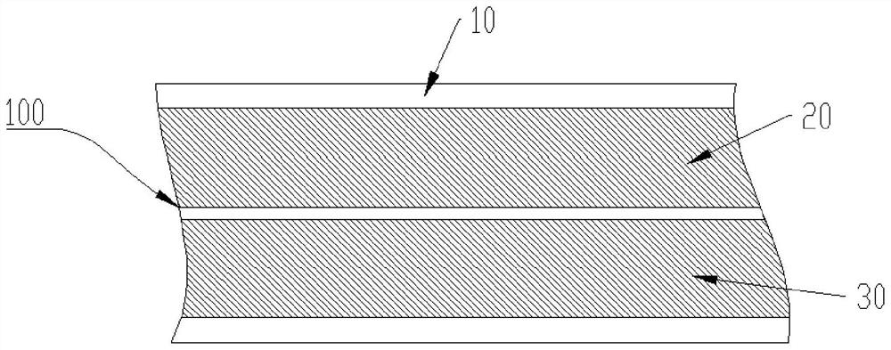
[0057] Such as figure 1 The first specific implementation of the pole piece shown includes: a current collector 10, and two coating areas are arranged at intervals on one side surface of the current collector 10, such as figure 1 As shown, the upper coating area is coated with the positive electrode layer 20 , and the lower coating area is coated with the negative electrode layer 30 .

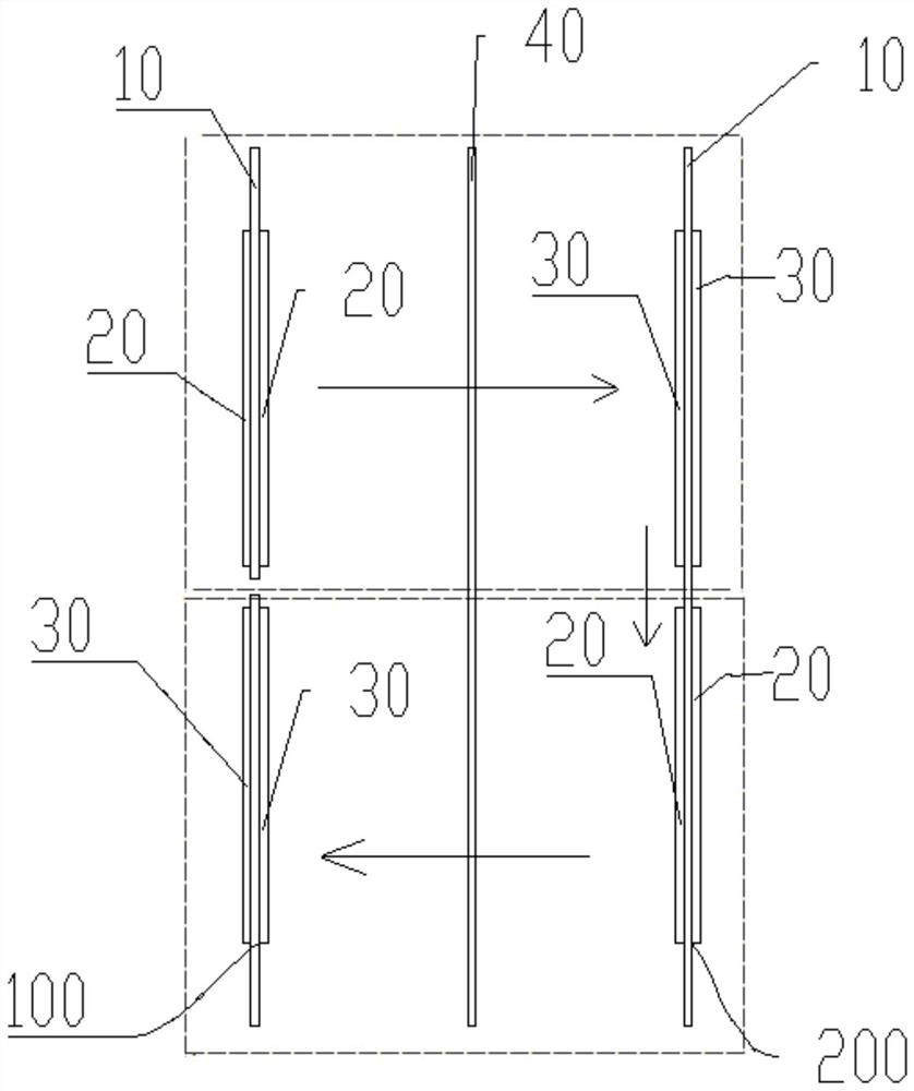
[0058] refer to figure 2 In the pole piece located on the left side of the figure, the positive electrode layer 20 and the negative electrode layer 30 are arranged at intervals from top to bottom on the left side of the current collector 10. Correspondingly, the right side of the current collector 10 is sequentially arranged from top to bottom A positive electrode layer 20 and a negative electrode layer 30 are arranged at intervals.

[0059] In this example, if figure 1 As shown, the current collector 10 between the positive electrode layer 20 and the negative electrode layer 30 is connecte...

Embodiment 2

[0062] Such as figure 1 The second specific embodiment of the pole piece shown includes: a current collector 10, and two coating areas are arranged at intervals on one side surface of the current collector 10, such as figure 1 As shown, the upper coating area is coated with the positive electrode layer 20 , and the lower coating area is coated with the negative electrode layer 30 .

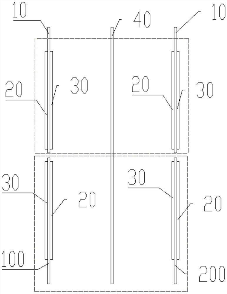
[0063] refer to image 3 In the pole piece located on the left side of the figure, the positive electrode layer 20 and the negative electrode layer 30 are arranged at intervals from top to bottom on the left side of the current collector 10. Correspondingly, the right side of the current collector 10 is sequentially arranged from top to bottom The negative electrode layer 30 and the positive electrode layer 20 are arranged at intervals.

[0064] In this example, if figure 1 As shown, the current collector 10 between the positive electrode layer 20 and the negative electrode layer 30 is connecte...

Embodiment 3

[0067] Such as Figure 4 The third specific embodiment of the pole piece shown includes: a current collector 10, and three coating areas are arranged at intervals on one side surface of the current collector 10, such as Figure 4 As shown, the positive electrode layer 20 , the negative electrode layer 30 and the positive electrode layer 20 are sequentially arranged in the three coating areas from top to bottom.

[0068] refer to Figure 5 In the pole piece located on the left side of the figure, the positive electrode layer 20, the negative electrode layer 30, and the positive electrode layer 20 are arranged at intervals from top to bottom on the left side of the current collector 10. Correspondingly, the right side of the current collector 10 is composed of The anode layer 20 , the anode layer 30 , and the anode layer 20 are sequentially arranged at intervals from top to bottom.

[0069] In this example, if Figure 4 As shown, the current collectors 10 between adjacent pos...


PUM


Abstract

The present invention provides a pole piece, a roll core and a battery, and belongs to the technical field of batteries. The pole piece comprises: a current collector, the surface of which is provided with a plurality of coating regions at intervals; a positive electrode layer and a negative electrode layer which are respectively arranged in the plurality of coating regions. According to the pole piece provided by the invention, the plurality of coating regions are arranged on the surface of the current collector at intervals, and the plurality of coating regions are respectively coated with the positive electrode layer or the negative electrode layer, that is, the positive electrode layer and the negative electrode layer are arranged on the single side surface of one current collector; compared with the prior art that one surface of one current collector only comprises a positive electrode layer or a negative electrode layer, and the current or voltage of a battery formed by processing the pole piece in the prior art is fixed under the condition of certain power. After the pole piece provided by the invention is processed to form a battery, under the condition that the power of the battery is fixed, the positive electrode layer and the negative electrode layer can be connected in series or in parallel differently to form a high-current battery or a high-voltage battery, so that the pole piece can be used in diversified occasions.

Description

technical field [0001] The invention relates to the technical field of batteries, in particular to a pole piece, a winding core and a battery. Background technique [0002] The coating process is a process of coating one or more layers of liquid active materials on the current collector, and then the coated liquid coating is dried or cured in an oven to form a film layer with special functions, which is the electrode layer , the electrode layer and the current collector are combined to form a pole piece. In the prior art, the positive electrode slurry is usually coated on both sides of the current collector, or the negative electrode slurry is coated on both sides, or the positive electrode slurry is coated on one side of the current collector and the other side of the same current collector. Negative electrode slurry, when preparing the battery, the positive electrode slurry and the negative electrode slurry are arranged oppositely, and a diaphragm is arranged between the ...

Claims


Application Information

Patent Timeline
Patent Type & Authority Applications(China)
IPC IPC(8): H01M4/13H01M4/70H01M10/0587H01M10/052
CPCH01M4/13H01M4/70H01M10/0587H01M10/052Y02E60/10Y02P70/50
Inventor 徐鑫朱卓平李核志
Owner 三一技术装备有限公司
Why Eureka
Try Eureka