
Camera baking real-time detection system and method

A real-time detection and camera technology, applied in the field of camera detection, can solve problems such as insufficient constant temperature time, loss of camera module manufacturers, abnormal baking temperature control, etc., to achieve guaranteed results, prevent human interference baking, and avoid baking abnormal effect

Pending Publication Date: 2021-12-31
江西盛泰精密光学有限公司
View PDF0 Cites 0 Cited by
  • Summary
  • Abstract
  • Description
  • Claims
  • Application Information

AI Technical Summary

Problems solved by technology

[0005] 2. The baking temperature control is abnormal, not within the baking temperature range, and the baking time is sufficient, resulting in insufficient constant temperature time
[0006] The above problems will affect the baking effect and camera module quality control, resulting in losses for camera module manufacturers

Method used


Image

  • Camera baking real-time detection system and method
  • Camera baking real-time detection system and method
  • Camera baking real-time detection system and method

Examples


Embodiment 1

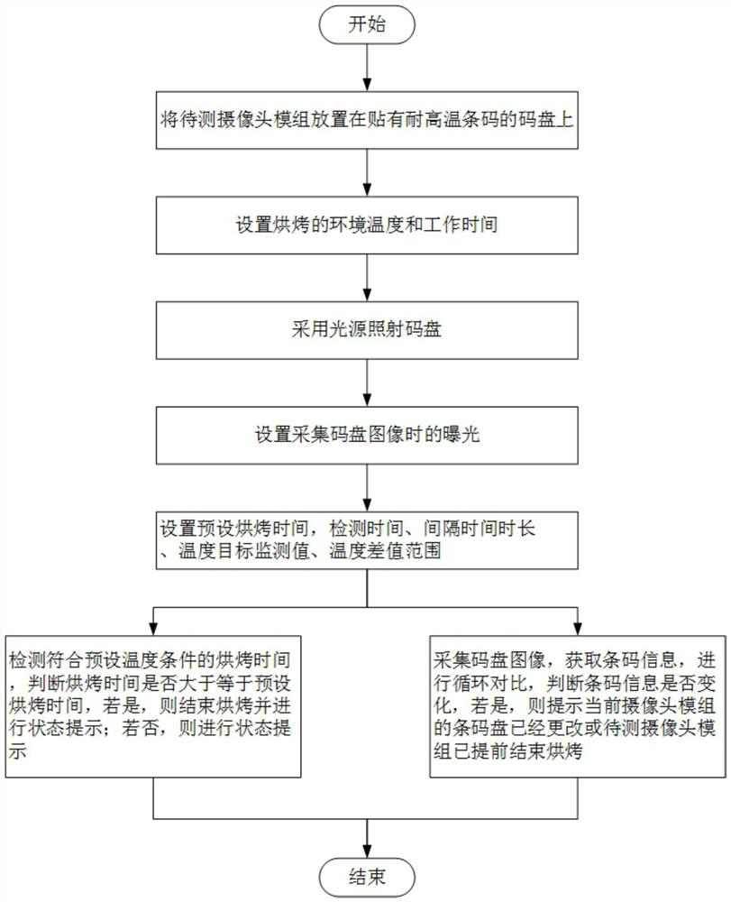
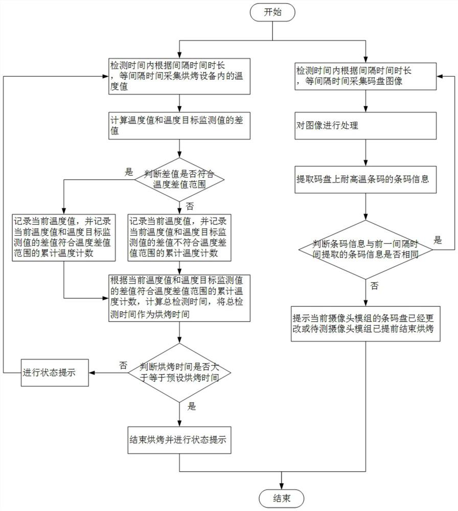
[0084] This embodiment is basically as attached figure 1 Shown: a camera baking real-time detection method, including the following content:

[0085] Place the camera module 3 to be tested on the code disc 2 with a high-temperature-resistant barcode, and bake the camera module 3 to be tested on the code disc 2, specifically: place the camera module 3 to be tested on the code disc 2 with a On the code disc 2 of the high-temperature-resistant barcode, when each group of camera modules 3 to be tested is placed, the high-temperature-resistant barcodes on the code disc 2 are different, ensuring that each group of camera modules 3 to be tested has a unique identification;

[0086] Set the ambient temperature and working time for baking; the ambient temperature is generally set to 20°C-80°C, and the working time is generally set to 4 hours to 24 hours. The specific ambient temperature and working time are based on the baking required by the camera module 3 to be tested Conditions ar...

Embodiment 2

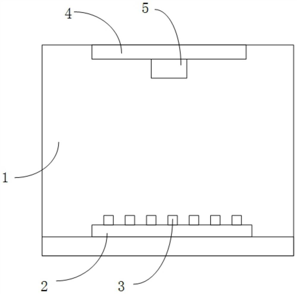
[0114] This implementation provides a camera baking real-time detection system, including: baking equipment 1, detection equipment and light source equipment 5;

[0115] A baking device 1 is used to bake the camera module 3 to be tested placed on the code disc 2 with a high-temperature-resistant barcode; in this embodiment, the baking device 1 is a baking oven;

[0116] The detection device is used to detect the baking time that meets the preset temperature conditions during the baking process, and judge whether the baking time is greater than or equal to the preset baking time. If yes, end the baking and give a status prompt; if not, then Carry out a status prompt; at the same time, collect the code disc 2 image, obtain the barcode information, and perform a cyclic comparison to determine whether the barcode information has changed. If so, it will prompt that the code disc 2 of the camera module to be tested has been changed or the camera module 3 to be tested has End the bak...


PUM


Abstract

The invention relates to the technical field of camera detection, in particular to a camera baking real-time detection system and method. The method comprises the steps: placing a to-be-detected camera module on a coded disc pasted with a high-temperature-resistant bar code, and baking the to-be-detected camera module on the coded disc; in the baking process, the baking time meeting the preset temperature condition is detected, whether the baking time is larger than or equal to the preset baking time or not is judged, if yes, baking is ended, and state prompting is carried out; if not, state prompting is carried out; Meanwhile, collecting a coded disc image, obtaining bar code information, performing cyclic comparison, judging whether the bar code information is changed or not, and if so, prompting that the coded disc of the current camera module to be detected is changed or the camera module to be detected has ended baking in advance. According to the scheme, manual interference of baking can be prevented, the constant temperature time is guaranteed, the baking effect and quality control of the camera module are guaranteed, and losses of camera module manufacturers are avoided.

Description

technical field [0001] The invention relates to the technical field of camera detection, in particular to a camera baking real-time detection system and method. Background technique [0002] At present, camera modules are widely used in mobile phones, tablets / notebooks, security, vehicle, medical, monitoring and other fields, and are used in various scenarios, including low temperature scenarios and high temperature scenarios. Therefore, in the camera module production process, the camera module baking experiment is an essential link. The camera module is baked to analyze various related issues, such as: lens field curvature, high temperature resistance test, eeprom aging, sensor resolution, module glue high temperature resistance test, etc. If there is a problem in the baking process, such as: inaccurate baking time, inaccurate baking, inaccurate baking temperature, etc., it may lead to customer complaints from the client to the camera module and the judgment of related pr...

Claims


Application Information

Patent Timeline
Patent Type & Authority Applications(China)
IPC IPC(8): H04N17/00G01M11/00
CPCH04N17/002G01M11/00
Inventor 胡露何健袁岩松林映庭宋凯静吴峰肖仁涛
Owner 江西盛泰精密光学有限公司
Learn More