Automatic plate feeding device for flexible circuit board electroplating line

A technology of flexible circuit boards and electroplating lines, applied in the direction of electrical components, electrical components, printed circuits, etc., to achieve the effects of high practicability, convenient operation and use, and fast loading efficiency

Active Publication Date: 2021-12-31
怀化海红盛电子科技有限公司
View PDF7 Cites 0 Cited by
  • Summary
  • Abstract
  • Description
  • Claims
  • Application Information

AI Technical Summary

Problems solved by technology

[0004] The present invention provides an automatic plate loading device for flexible circuit board electroplating line, which solves the problems in the above-mentioned background technology

Method used


Image

  • Automatic plate feeding device for flexible circuit board electroplating line
  • Automatic plate feeding device for flexible circuit board electroplating line
  • Automatic plate feeding device for flexible circuit board electroplating line

Examples


Embodiment 1

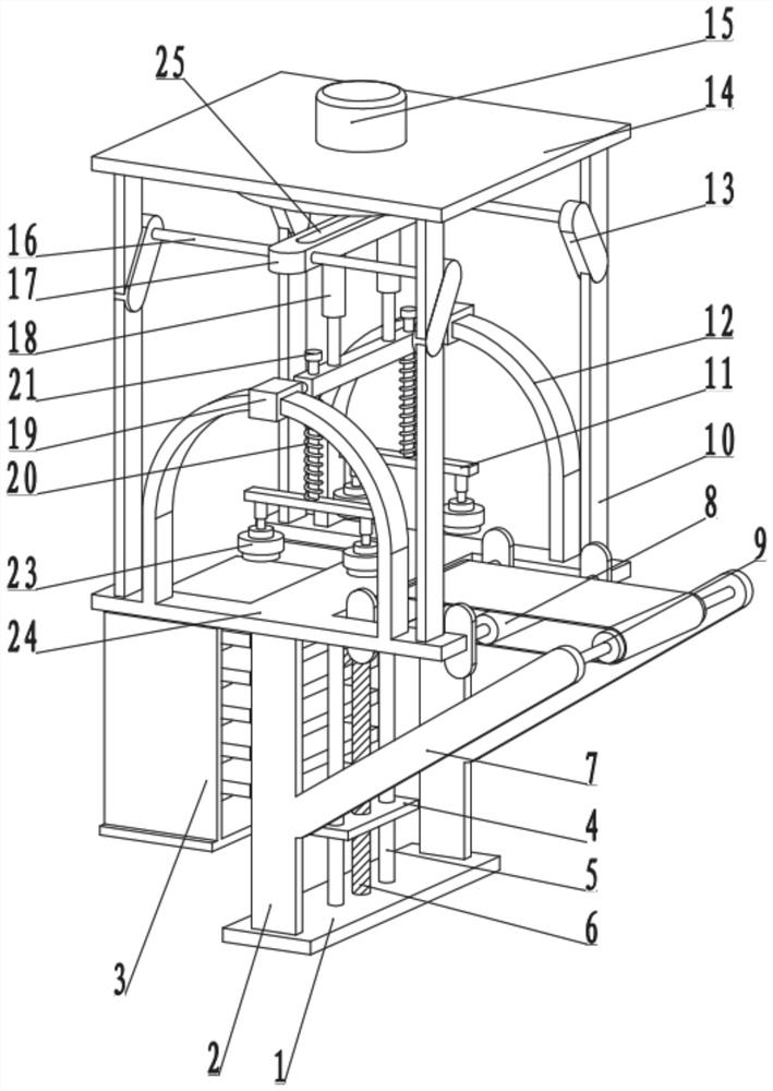
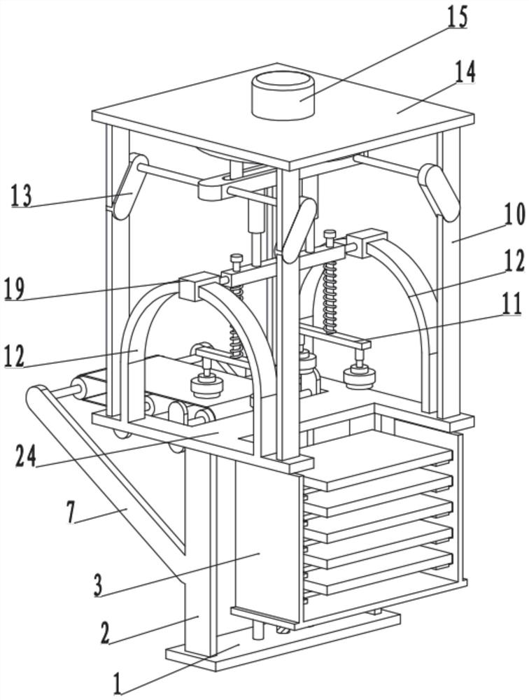
[0028] see Figure 1-5 , an automatic board loading device for a flexible circuit board electroplating line, including a base plate 1, and also includes:

[0029] The support plate 2 fixedly arranged on both sides of the bottom plate 1, the top of the support plate 2 is fixedly connected to the bearing plate 24, and the top plate 14 is arranged above the bearing plate 24;

[0030] The upper plate mechanism arranged between the top plate 14 and the carrying plate 24 includes slide rails 12 fixedly arranged on both sides of the carrying plate 24, the slide rails 12 are U-shaped structures, and sliding blocks 19 are sleeved on the slide rails 12, Carrying beams 28 are arranged between the sliding blocks 19, and the two sides of the carrying beams 28 are rotationally connected with the sliding blocks 19. The two sides of the carrying beams 28 slide through and set the piston rods 21, and the bottom of the piston rods 21 is fixedly provided with a mounting rod 11. An elastic membe...

Embodiment 2

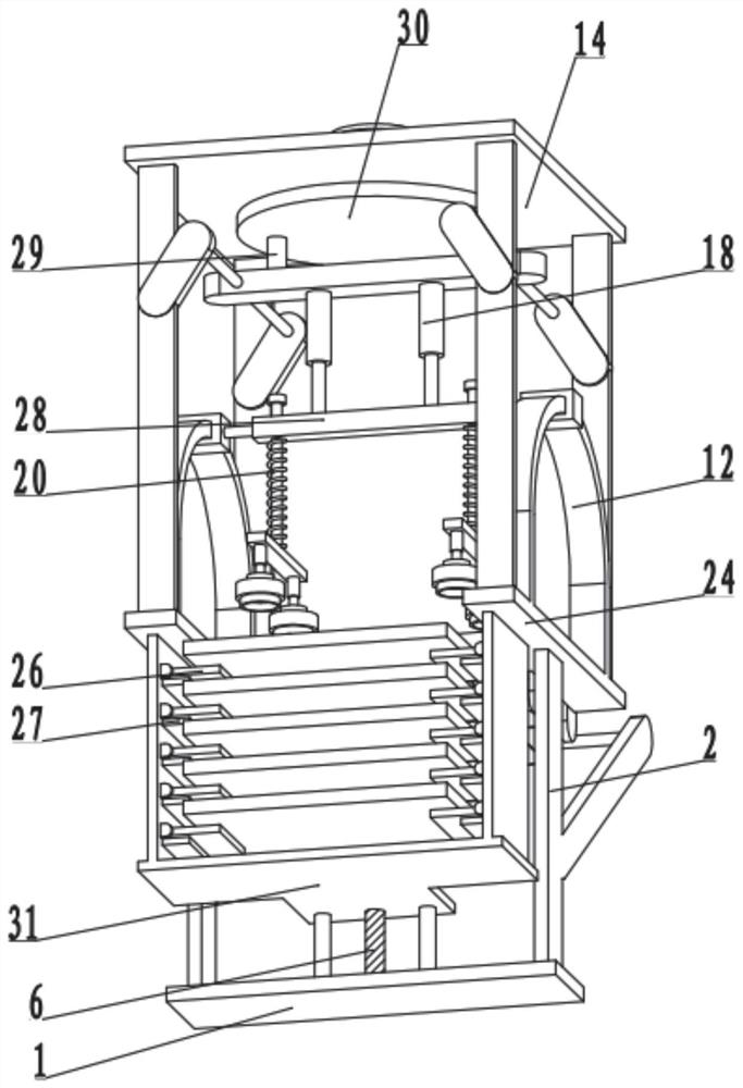
[0034] see Figure 1-5 , the other content of this embodiment is the same as that of Embodiment 1, the difference is that: the drive assembly includes a drive disc 30 rotatably arranged at the bottom of the top plate 14, one side of the bottom of the drive disc 30 is fixedly connected to the fixed shaft 29, and the bottom side of the fixed shaft 29 is A movable beam 17 is provided, and a chute 25 is provided on the movable beam 17 , and the fixed shaft 29 extends into the chute 25 and is in sliding contact with the movable beam 17 .

[0035] The top plate 14 on both sides of the movable beam 17 and the bearing plate 24 are fixedly connected to the support rod 10, one side of the support rod 10 is fixedly connected to the mounting block 13, and the mounting blocks 13 are fixedly connected to the bearing column 16, and the bearing column 16 slides through the On the movable beam 17 , a telescopic tube 18 is fixedly arranged between the movable beam 17 and the bearing beam 28 . ...


PUM


Abstract

The invention discloses an automatic plate feeding device for a flexible circuit board electroplating line, and relates to the technical field of circuit boards. The automatic plate feeding device comprises a bottom plate, and further comprises: supporting plates arranged on the two sides of the bottom plate, wherein the tops of the supporting plates are fixedly connected with a bearing plate, and a top plate is arranged above the bearing plate; a plate feeding mechanism arranged between the top plate and the bearing plate and comprising sliding rails arranged on the two sides of the bearing plate, wherein the sliding rails are of U-shaped structures, the sliding rails are slidably sleeved with sliding blocks, a bearing beam is arranged between the sliding blocks, the two sides of the bearing beam are rotationally connected with the sliding blocks, piston columns are slidably arranged on the two sides of the bearing beam in a penetrating mode, mounting rods are arranged at the bottoms of the piston columns, suction cups are arranged on the two sides of the bottoms of the mounting rods, a driving assembly is arranged on the top plate above the bearing beam and drives the bearing beam to slide on the sliding rails in a reciprocating mode, and material conversion is achieved under the combined action of the suction cups; a feeding mechanism arranged on one side of the bearing plate; and a conveying mechanism arranged on one side of the bearing plate and is used for conveying the circuit board.

Description

technical field [0001] The invention relates to the technical field of circuit boards, in particular to an automatic board loading device for a flexible circuit board electroplating line. Background technique [0002] Flexible circuit boards are printed circuits made of flexible insulating substrates. Flexible circuits provide excellent electrical performance, can meet the design needs of smaller and higher-density installations, and also help reduce assembly processes and enhance reliability. Flexible circuits Boards are also integral and important components in the production of microelectronics. [0003] In the process of production and processing of flexible circuit boards, automatic board loading devices are required. The process of traditional board loading devices is relatively complicated when loading boards, and manual transfer and loading are required, and then the board is assisted by the board loading device. Operation Not only is it cumbersome, but the work eff...

Claims


Application Information

Patent Timeline
Patent Type & Authority Applications(China)
IPC IPC(8): H05K13/00H05K3/18
CPCH05K13/0076H05K3/188Y02P10/20
Inventor 胡佳杰
Owner 怀化海红盛电子科技有限公司
Why Eureka
Try Eureka