Lumbar vertebra minimally invasive surgery postoperative leg straightening, lifting and instep hooking auxiliary exercise bed
A technique of minimally invasive surgery and leg straightening, which is applied to massage auxiliary products, sports accessories, gymnastics equipment, etc. It can solve problems such as difficulty in controlling the strength, time-consuming and labor-intensive, and achieve the effect of saving manpower
- Summary
- Abstract
- Description
- Claims
- Application Information
AI Technical Summary
Problems solved by technology
Method used
Image
Examples
Embodiment 1
[0038] A kind of lumbar spine minimally invasive surgery postoperative straight leg raising hook instep auxiliary exercise bed, such as figure 1 , image 3 , Figure 4 with Figure 5 As shown, it includes a base 1, a housing 2, a support plate 4, a control board 5, a supporting mechanism 6 and a leg lifting mechanism 7, a base 1 is provided on the lower right side of the housing 2, and a support is provided on the left side of the top of the housing 2. Plate 4, the right front side of the top of the support plate 4 is provided with a control panel 5, the right side of the support plate 4 is provided with a supporting mechanism 6, and a leg lifting mechanism 7 is provided between the supporting plate 4 and the supporting mechanism 6.
[0039]The supporting mechanism 6 includes a fixed plate 61, a hinged shaft 62 and a hinged plate 63. Two fixed plates 61 are connected to the front and rear sides of the bottom of the right side of the support plate 4. The fixed plates 61 are l...
Embodiment 2
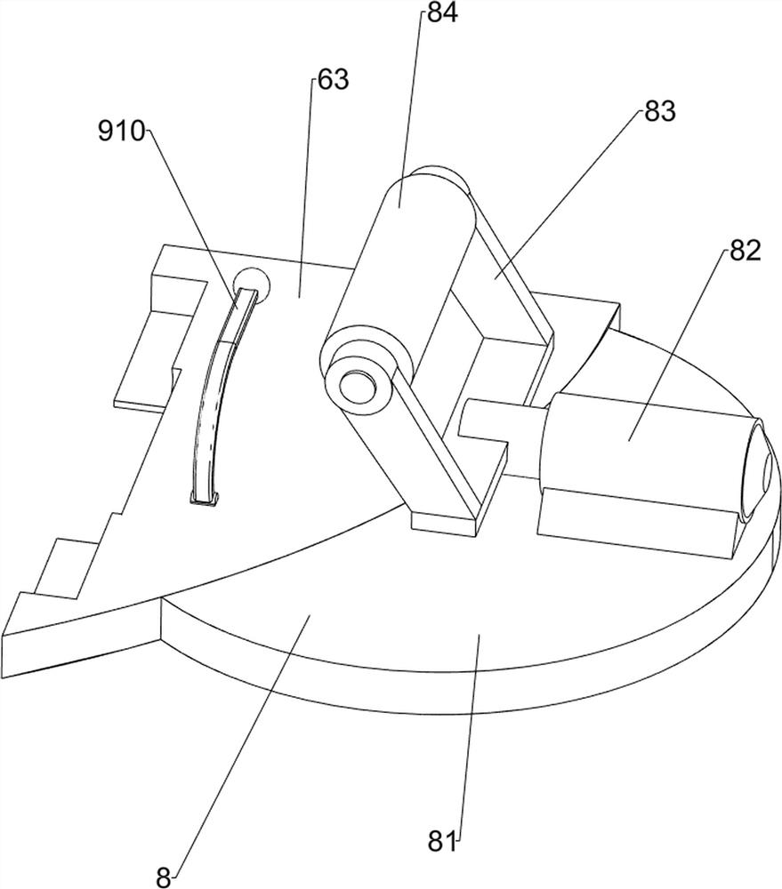
[0043] On the basis of Example 1, such as figure 1 , figure 2 with Figure 6-Figure 16 Shown, also include footboard booster mechanism 8, footboard booster mechanism 8 includes extension plate 81, the first electric push rod 82, support 83 and rubber roller 84, all be provided with extension plate 81 in the middle of hinged plate 63 right ends, extension plate 81 The top right side is all provided with first electric push rod 82, and first electric push rod 82 telescopic rod left sides are all provided with support 83, and support 83 tops are all rotatably connected with rubber roller 84.
[0044] After the patient is lying down, fit the feet to the bracket 83. After people press the switch key, the control module receives the signal and sends the signal to the first electric push rod 82, so that the telescopic rod of the first electric push rod 82 is stretched to drive the bracket 83 and the rubber roller 84 move to the left, so that the rubber roller 84 rolls on the patie...
Embodiment 3
[0056] On the basis of Example 2, such as figure 1 , Figure 5 , Figure 6 , Figure 7 , Figure 8 , Figure 17 and Figure 18 As shown, a control box 3 is also included. The left side of the housing 2 is provided with a control box 3. The control box 3 includes a battery, a control module and a power module. The battery supplies power to the entire device. The power module is connected to a main power switch through a line , the control module and the power module are electrically connected, the control module is electrically connected to the DS1302 circuit and the 24C02 circuit; the first contact switch 92 and the second contact switch 96 are electrically connected to the control module, the switch, the two-pin mode, The one-leg mode and the reset key are connected to the control module through an electrical connection; the electromagnet 98, the first electric push rod 82, the second electric push rod 104 and the reduction motor 72 are connected to the control module th...
PUM
 Abstract
Description
Claims
Application Information
 - R&D
- Intellectual Property
- Life Sciences
- Materials
- Tech Scout
- Unparalleled Data Quality
- Higher Quality Content
- 60% Fewer Hallucinations
Browse by: Latest US Patents, China's latest patents, Technical Efficacy Thesaurus, Application Domain, Technology Topic, Popular Technical Reports.
© 2025 PatSnap. All rights reserved.Legal|Privacy policy|Modern Slavery Act Transparency Statement|Sitemap|About US| Contact US: help@patsnap.com


