
Uniform dispersion equipment for coating production

A uniform dispersion and equipment technology, applied in the direction of dissolving, mixing machines, chemical instruments and methods, etc., can solve the problems of easy sticking of raw materials to the inner wall of the dispersion tank, waste of resources, increase of labor intensity, etc., to prevent waste of raw material resources, The effect of reducing workload and avoiding waste

Pending Publication Date: 2022-01-04
江西亿彩涂料股份有限公司
View PDF0 Cites 7 Cited by
  • Summary
  • Abstract
  • Description
  • Claims
  • Application Information

AI Technical Summary

Problems solved by technology

[0004] In order to overcome the shortcomings of the existing uniform dispersion equipment for paint production, raw materials are easy to stick to the inner wall of the dispersion tank, resulting in waste of resources, manual addition of emulsifiers, and increased labor intensity. The technical problem of the present invention is to provide a Uniform dispersion equipment for coating production with raw materials and scraping effect

Method used


Image

  • Uniform dispersion equipment for coating production
  • Uniform dispersion equipment for coating production
  • Uniform dispersion equipment for coating production

Examples


Embodiment 1

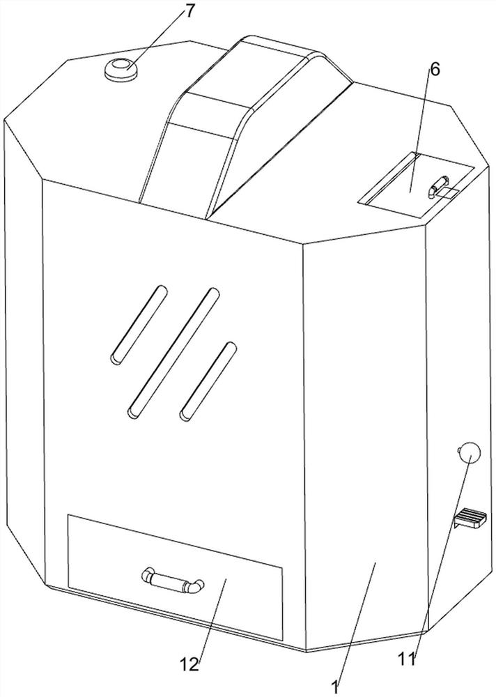
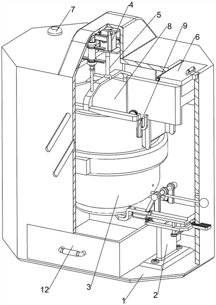
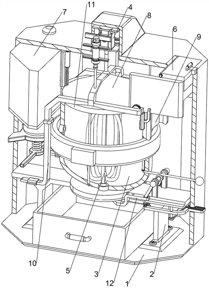
[0037] A uniform dispersion equipment for coating production, such as figure 1 , figure 2 , image 3 , Figure 4 , Figure 5 , Image 6 , Figure 7 with Figure 8 As shown, it includes a casing 1, a bracket 2, a storage tank 3, a servo motor 4, a stirring paddle 5, an opening and closing mechanism 6, and an adding mechanism 7. A storage tank 3 is installed between the inner sides of the housing 1, a servo motor 4 is installed in the middle of the upper side of the housing 1, and a stirring paddle 5 is connected to the output shaft of the servo motor 4. The lower side of the stirring paddle 5 is located inside the storage tank 3, and the top of the housing 1 An opening and closing mechanism 6 is arranged on the right side, and an adding mechanism 7 is installed on the upper left side inside the casing 1 .

[0038] The opening and closing mechanism 6 includes a cover plate 61, a magnet block 62, a first rotating shaft 63 and a first torsion spring 64. The right side of the...

Embodiment 2

[0042] On the basis of Example 1, such as figure 1 , figure 2 , image 3 , Figure 9 , Figure 10 , Figure 11 , Figure 12 , Figure 13 , Figure 14 , Figure 15 , Figure 16 , Figure 17 with Figure 18 As shown, it also includes a splash-proof assembly 8. The splash-proof assembly 8 includes a cylinder 81, a connecting rod 82 and a splash guard 83. A cylinder 81 is installed symmetrically front and back in the middle of the upper side of the interior of the housing 1. Between the lower side of the telescopic rod of the cylinder 81 A connecting rod 82 is connected, and the connecting rod 82 is rotationally connected with the stirring paddle 5 , and a splash guard 83 is installed at the bottom of the connecting rod 82 .

[0043] Also includes a guide assembly 9, the guide assembly 9 includes an engaging rod 91, a fixed plate 92, a guide rail 93, a swivel seat 94, a second rotating shaft 95, a gear 96, a rack 97, a guide plate 98 and a second torsion spring 99, con...


PUM


Abstract

The invention relates to dispersion equipment, in particular to uniform dispersion equipment for coating production. The technical problem to be solved by the invention is to provide the uniform dispersion equipment for coating production, which can automatically add raw materials and has a scraping effect. The uniform dispersion equipment for coating production comprises: a shell; supports which are symmetrically arranged on the lower side of the interior of the shell; a placing tank which is arranged between the inner side of the upper part of the bracket and the inner side of the shell; a servo motor which is arranged in the middle of the upper side in the shell; and a stirring paddle which is arranged on an output shaft of the servo motor, wherein the lower side of the stirring paddle is located on the inner side of the placing tank. When the raw materials are placed in the storage tank, people repeatedly pull a pull rope, and under the action of the elastic force of a third spring, a material scraping ring moves up and down to downwards scrape the raw materials adhered in the storage tank, so that the material scraping effect is achieved, waste is avoided, and the workload of workers is effectively reduced.

Description

technical field [0001] The invention relates to a dispersing device, in particular to a uniform dispersing device for coating production. Background technique [0002] The traditional name of paint is paint, which can be applied to the surface of the object to be protected, which plays a role of protection or decoration. In order to make the paint better colored, it is usually necessary to stir and disperse the raw materials of the paint to enhance the coloring effect. Effect, in the existing uniform dispersion equipment for paint production, during the process of stirring paint raw materials, the raw materials are easy to stick to the inner wall of the dispersion tank, resulting in waste of resources, and it is necessary to manually add emulsifiers, increasing labor intensity, one-time output It is easy to cause waste of emulsifier, and there is no intermittent discharge effect, resulting in a decrease in work efficiency. [0003] To sum up, it is necessary to design a uni...

Claims


Application Information

Patent Timeline
Patent Type & Authority Applications(China)
IPC IPC(8): B01F27/96B01F35/12B01F35/75B01F101/30
Inventor 黄清卫黄诚
Owner 江西亿彩涂料股份有限公司
Learn More