Cleaning device with pre-drying function for traditional Chinese medicine decoction piece processing
A technology of traditional Chinese medicine decoction pieces and cleaning device, which is applied in the direction of using liquid cleaning method, drying, drying machine, etc., can solve the problems of low efficiency, high humidity of the decoction pieces, inability to achieve comprehensive cleaning, etc., and achieves reduction of labor intensity and humidity. Effect
- Summary
- Abstract
- Description
- Claims
- Application Information
AI Technical Summary
Problems solved by technology
Method used
Image
Examples
Embodiment 1
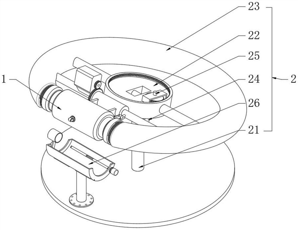
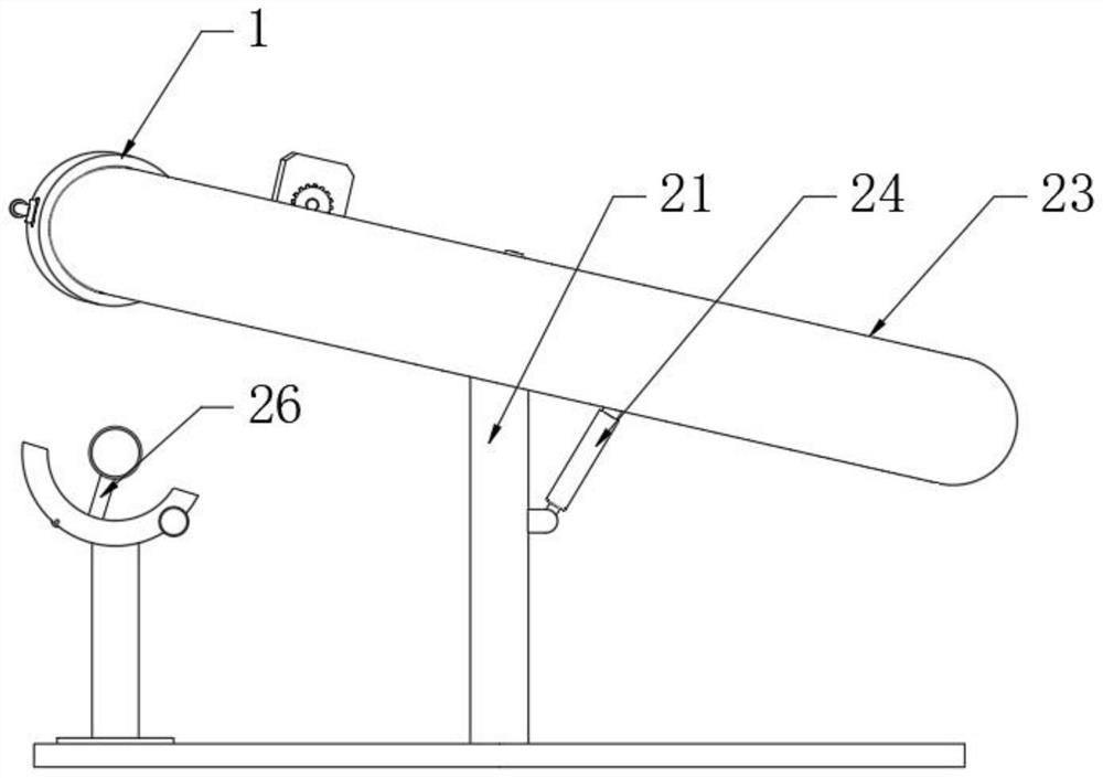
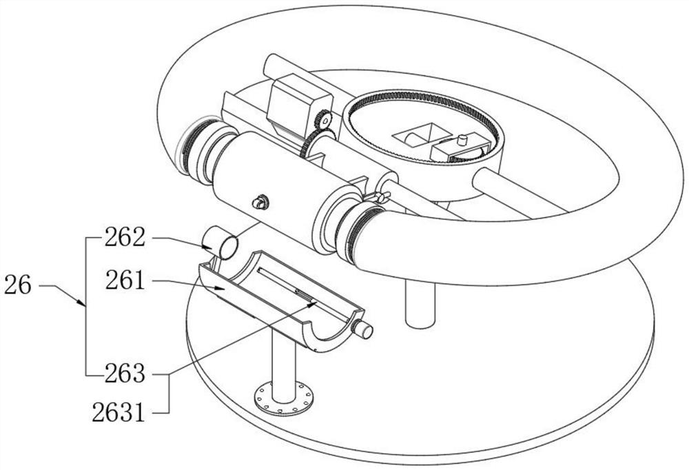
[0030] see Figure 1-6, a cleaning device with a pre-drying function for processing Chinese herbal pieces, comprising a decoction piece tube 1 and a cleaning part 2, the decoction piece tube 1 is used to fill the Chinese medicine decoction pieces, the tube wall of the decoction piece tube 1 is a non-hollow structure, and the cleaning part 2 The function of cleaning the decoction pieces of traditional Chinese medicine, in the technical solution of this embodiment, the cleaning part 2 and the decoction piece tube 1 are combined to form a closed mechanism, which can not only fully clean the decoction pieces, but also facilitate loading and unloading, and also has the function of pre-drying; Specifically, the cleaning part 2 includes a bearing column 21, a positioning plate 22, a C-shaped cleaning pipe 23, a driving cylinder 24, a driving shaft 25, and a drying assembly 26. The axis is horizontal, and a relief hole can be provided in the middle part of the positioning plate 22, an...
Embodiment 2
[0032] see Figure 5 and Figure 6 , in Embodiment 1, the loading and unloading of the decoction piece cartridge 1 requires manual handling or external lifting equipment to complete the docking and separation with the C-shaped cleaning pipe 23, which is labor-intensive or costly. The present embodiment and Embodiment 1 The difference is that the cleaning part 2 also includes a bearing sleeve 27, a locking shaft 28 and a driving member 29. The bearing sleeve 27 is rotatably connected in the C-shaped ring of the C-shaped cleaning pipe 23, and the rotation axis of the bearing sleeve 27 is parallel to the axis of the positioning tube 232. The outer wall of the carrying sleeve 27 is fixedly provided with a positioning insert 271, and the locking shaft 28 runs through one side of the positioning insert 271 and is connected in rotation. The integrated recessed socket 12 used in conjunction with the positioning insert 271 and the integrated recessed hanging groove 13 used in conjunct...
Embodiment 3
[0034] see Figure 5 and Figure 6 The difference from Embodiment 2 is that the outer wall of the support shaft 233 is fixedly provided with a limit shaft 2331 with one end facing the direction of the notch of the C-shaped cleaning pipe 23. The limit shaft 2331 and the C-shaped cleaning pipe 23 are in the same plane, and the locking shaft 28 One end of the rotating arm 282 is fixedly arranged, and the rotating arm 282 and the hanging rod 281 are in the same plane. The free end of the rotating arm 282 is rotatably connected with a connecting column 2821 which is vertically distributed between the axis and the rotating arm 282, and the limit shaft 2331 runs through the connecting column 2821. and is a sliding fit, so when the positioning flashboard 271 tilts upwards, under the limit of the limit shaft 2331, the locking shaft 28 rotates, and the hanging rod 281 moves upwards and breaks away from the recessed hanging groove 13, otherwise when the positioning flashing plate When 2...
PUM
 Abstract
Description
Claims
Application Information
 - R&D
- Intellectual Property
- Life Sciences
- Materials
- Tech Scout
- Unparalleled Data Quality
- Higher Quality Content
- 60% Fewer Hallucinations
Browse by: Latest US Patents, China's latest patents, Technical Efficacy Thesaurus, Application Domain, Technology Topic, Popular Technical Reports.
© 2025 PatSnap. All rights reserved.Legal|Privacy policy|Modern Slavery Act Transparency Statement|Sitemap|About US| Contact US: help@patsnap.com


