Eureka AIR delivers breakthrough ideas for toughest innovation challenges, trusted by R&D personnel around the world.

Wafer fixing ring and CMP equipment with same

A wafer fixing and grinding ring technology, which is used in metal processing equipment, grinding/polishing equipment, manufacturing tools, etc., can solve problems such as affecting the quality of wafer grinding, and achieve the effect of avoiding the impact and improving the overall quality.

Pending Publication Date: 2022-01-04
BEIJING SEMICORE PRECISION MICROELECTRONICS EQUIP CO LTD
View PDF7 Cites 1 Cited by
  • Summary
  • Abstract
  • Description
  • Claims
  • Application Information

AI Technical Summary

Problems solved by technology

[0004] Therefore, the technical problem to be solved in the present invention is to overcome the defect that the residue accumulation in the polishing pad groove of the CMP wafer retaining ring in the prior art can affect the subsequent wafer polishing quality, thereby providing a wafer retaining ring and CMP equipment with its

Method used


Image

  • Wafer fixing ring and CMP equipment with same
  • Wafer fixing ring and CMP equipment with same
  • Wafer fixing ring and CMP equipment with same

Examples


Embodiment 1

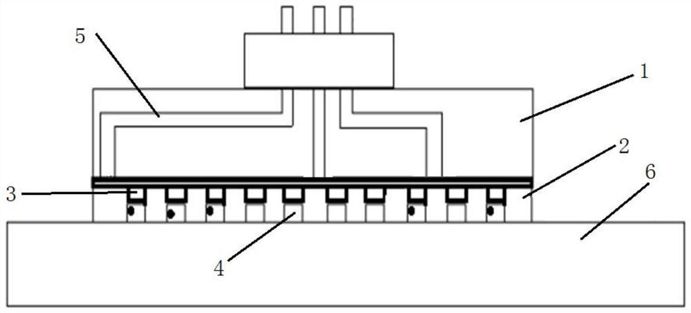
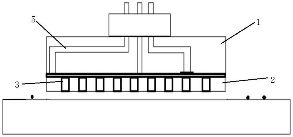
[0036] like Figure 1 to Figure 4 Shown is a wafer fixing ring provided by this embodiment, wherein figure 1 and figure 2 Solid black dots in are residues. It includes: a support ring 1 as a support, a grinding ring 2 and a telescopic assembly 3 installed between the support ring 1 and the grinding ring 2 .

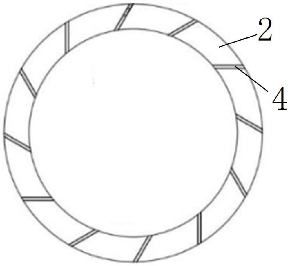
[0037] The support ring 1 and the grinding ring 2 are arranged coaxially, and the inner circle of the support ring 1 is the same diameter as the inner circle of the grinding ring 2, and the outer circle of the support ring 1 is the same diameter as the outer circle of the grinding ring 2. The grinding ring 2 is installed on one side of the support ring 1 in parallel, and a plurality of grooves 4 are arranged at intervals on the grinding ring 2 , the grooves 4 extend toward the support ring 1 and the grooves 4 pass through the grinding ring 2 .

[0038] The telescopic assembly 3 is installed between the support member and the grinding ring 2 , and the telescopic assemb...

Embodiment 2

[0047] This embodiment provides a CMP device with the wafer fixing ring described in Embodiment 1. When cleaning the wafer fixing ring, control the expansion of the telescopic assembly in the groove to a clean state, so that the telescopic assembly fills the groove and pushes out the residue in the groove. With high-pressure water spray cleaning, it can be quickly and easily removed The removal of the grinding residue in the groove can prevent the grinding residue in the groove from affecting the subsequent grinding and polishing wafers, and can greatly improve the overall quality of all wafers in the entire batch.


PUM


Abstract

The invention relates to the technical field of semiconductor CMP processing, in particular to a wafer fixing ring and CMP equipment with the same. The wafer fixing ring comprises a support part, a grinding ring installed on one side of the supporting part in parallel and telescopic assemblies, wherein a plurality of grooves are formed in the grinding ring at intervals, the grooves extend towards a supporting ring and penetrate through the grinding ring, and the telescopic assemblies are installed between the supporting part and the grinding ring, and the telescopic assemblies have a cleaning state in which the telescopic assemblies extend into the grooves to completely fill the grooves and a grinding state in which the telescopic assemblies are withdrawn from the grooves. During cleaning, the telescopic assemblies are controlled to extend to the cleaning state in the grooves, so that the telescopic assemblies fills the grooves and push out residues in the grooves at the same time, high-pressure water spraying cleaning matches, the grinding residues in the grooves can be rapidly and conveniently removed, influences of the grinding residues in the grooves on subsequent grinding and polishing wafers can be avoided, and the overall quality of all wafers in the whole batch can be greatly improved.

Description

technical field [0001] The invention relates to the technical field of semiconductor CMP processing, in particular to a wafer fixing ring and CMP equipment provided with it. Background technique [0002] CMP (Chemical Mechanical Planarization) is a chemical mechanical polishing process that uses chemical etching and mechanical force to planarize silicon wafers or other substrate materials during processing. During the chemical mechanical polishing process of modern semiconductor production, the fixed ring on the polishing head is used to keep the wafer in the ring during the grinding process of manufacturing semiconductor wafers so as to grind one side of the wafer. Traditional retaining ring surfaces consist of a fixed number and size of grooves, which limit the escape of slurry by-products. [0003] After the CMP chemical etching solution reacts with the metal on the surface of the wafer, it will produce corresponding by-product residues. The by-products will be discharge...

Claims


Application Information

Patent Timeline
Patent Type & Authority Applications(China)
IPC IPC(8): B24B37/32B24B55/06B24B37/10B24B7/22
CPCB24B37/32B24B55/06B24B37/10B24B7/228
Inventor 唐强蒋锡兵
Owner BEIJING SEMICORE PRECISION MICROELECTRONICS EQUIP CO LTD
Why Eureka
Eureka Blog
Learn More