Gas path system for rotor system of micro gas turbine and micro gas turbine

A technology of micro gas turbine and gas circuit system, which is applied in the direction of gas turbine device, engine lubrication, machine/engine, etc. It can solve problems affecting stability and gas film shape fluctuations, so as to prolong service life, switch smoothly, and ensure stable operation sexual effect

Pending Publication Date: 2022-01-04
刘慕华
View PDF0 Cites 2 Cited by
  • Summary
  • Abstract
  • Description
  • Claims
  • Application Information

AI Technical Summary

Problems solved by technology

However, at the moment when the dynamic and static pressure state of the air bearing is switched, the air film shape will fluctuate, which will affect the stability
Therefore, it is necessary to develop a solution to solve the problem of fluctuations in the "air film shape" at the moment of switching between the dynamic and static pressure states of the air bearing

Method used


Image

  • Gas path system for rotor system of micro gas turbine and micro gas turbine
  • Gas path system for rotor system of micro gas turbine and micro gas turbine
  • Gas path system for rotor system of micro gas turbine and micro gas turbine

Examples


Embodiment 1

[0033] Embodiment 1 Gas path system for micro gas turbine rotor system and micro gas turbine

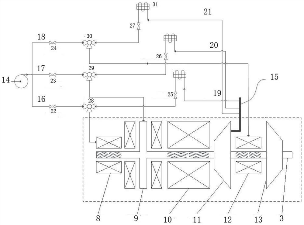
[0034] A gas path system for a micro gas turbine rotor system, the rotor system includes a rotating shaft 3, on which a first radial bearing 8, a first thrust bearing 9, a motor 10, a compressor 11, and a second radial bearing are sequentially arranged 12 and turbo 13, such as figure 1 As shown, the first radial bearing 8, the first thrust bearing 9, and the second radial bearing 12 are all air bearings (dynamic pressure bearings or dynamic and static pressure hybrid bearings); the compressor 11 may include a compressor impeller and a diffuser.

[0035]The air circuit system includes an air pump 14, an air source air circuit, a self-static pressure supplementary air circuit and a tee, wherein the input end of the air pump 14 communicates with the air source, and the output end of the air pump 14 communicates with the input end of the air source air circuit. Connected, the output end...

Embodiment 2

[0050] Embodiment 2 Carry out the control method of self-static pressure air supplement

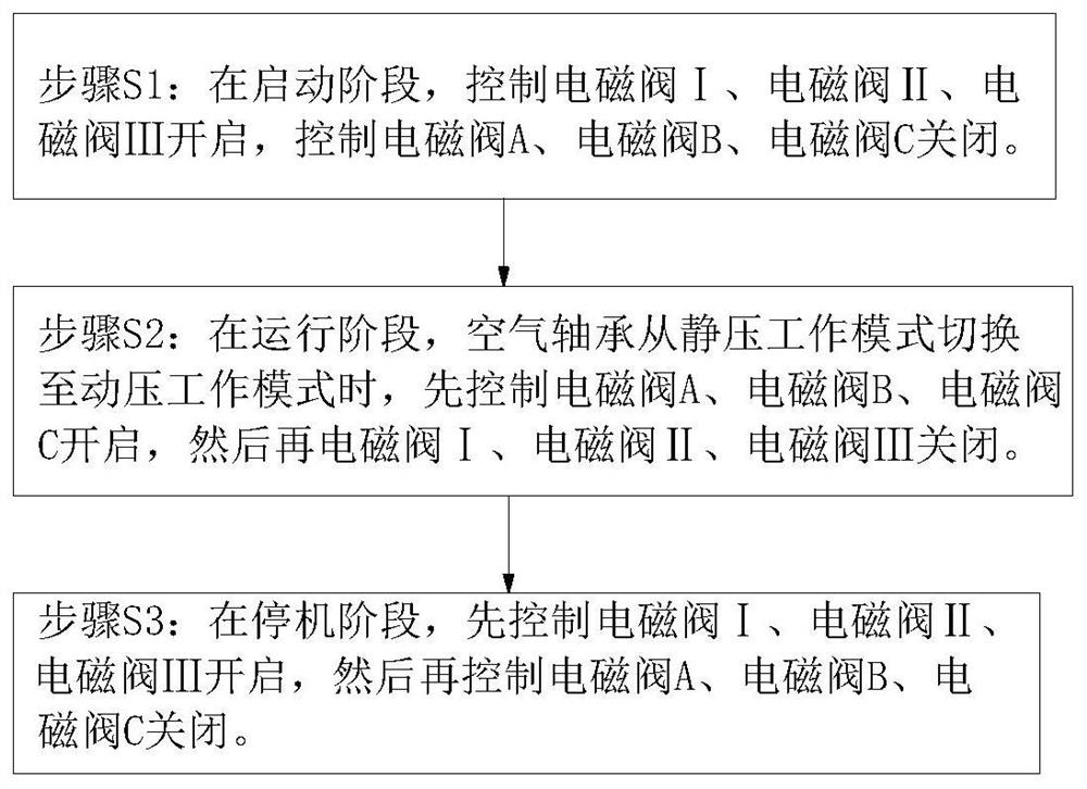
[0051] The control method for self-static pressure supplementary air by using the air circuit system of Embodiment 1 includes the steps: when the air bearing in the rotor system is switched from the static pressure working mode to the dynamic pressure working mode, firstly control the opening of the self-static pressure supplementary air circuit , and then control the gas source and gas path to close. In this way, when the air bearing in the rotor system is switched from the static pressure working mode to the dynamic pressure working mode, the high-pressure gas provided by the compressor is introduced as the supplementary air source, realizing self-static pressure supplementation at the moment of performing the dynamic and static pressure state switching of the air bearing The effect of the air film balances the shape fluctuation of the air film of the air bearing caused by the stop of t...

Embodiment 3

[0061] Embodiment 3 Gas path system for micro gas turbine rotor system and micro gas turbine

[0062] The structure is the same as in Embodiment 1, the difference is that two radial bearings and two thrust bearings are arranged on the rotating shaft, both of which are air bearings (dynamic pressure bearings or dynamic and static pressure mixed air bearings), and correspondingly, there are four tees , the air source air path and the self-static pressure air supply air path each include 4 branch air paths, the two branch air paths supplying air to the same air bearing meet through the tee, and then supply air to the corresponding air bearing.


PUM


Abstract

The invention discloses a gas path system for a rotor system of a micro gas turbine. The rotor system at least comprises a gas compressor, a turbine and at least one set of air bearings, and the gas compressor, the turbine and the air bearings are coaxially arranged. The gas path system comprises a gas source gas path and a self-static pressure gas supplementing gas path, wherein the input end of the gas source gas path communicates with a gas source, and the output end of the gas source gas path communicates with a gas inlet port of the air bearings; and the input end of the self-static-pressure gas supply gas path communicates with an outlet of the gas compressor, and the output end of the self-static-pressure gas supply gas path communicates with the gas inlet port of the air bearings. The invention further discloses a micro gas turbine with the gas path system. The invention further discloses a control method for achieving self-static-pressure gas supply through the gas path system. When dynamic and static pressure working states of the air bearings of a rotor are switched, the gas compressor is introduced to serve as a supplementary gas source, self-static pressure gas supplementation is achieved, and the form fluctuation of a gas film of the air bearings at the switching moment can be balanced, so that stable switching is guaranteed, and the stability of the working state of the rotor system is kept.

Description

technical field [0001] The invention relates to a gas path system for a micro gas turbine rotor system and a micro gas turbine, belonging to the technical field of micro gas turbines. Background technique [0002] The micro gas turbine uses continuously flowing gas as the working medium to drive the impeller to rotate at high speed, and convert the energy of the fuel into useful work. It is a rotating impeller heat engine. It mainly includes three parts: compressor, combustion chamber and turbine. The compressor sucks in air from the external atmosphere and compresses it to pressurize it. At the same time, the temperature of the air also increases accordingly; Mixed combustion generates high-temperature and high-pressure gas; then it enters the turbine and expands to do work, pushing the turbine to drive the compressor and the external load rotor to rotate together at high speed, realizing the partial conversion of the chemical energy of the gas or liquid fuel into mechanica...

Claims


Application Information

Patent Timeline
Patent Type & Authority Applications(China)
IPC IPC(8): F16C32/06F02C7/06F02C3/04
CPCF16C32/0614F16C32/067F02C7/06F02C3/04
Inventor 靳普
Owner 刘慕华
Why Eureka
Try Eureka