Supercharge Your Innovation With Domain-Expert AI Agents!

System and method for remotely controlling actuator based on network signal of Ethernet

A network signal and remote control technology, applied in the field of network signal remote control actuator system, can solve the problems of slow communication speed of 4-20mA output circuit, many types of output cards, easy to be interfered, etc., to achieve convenient and flexible use, Simplify the output card, the effect of strong anti-interference ability

Pending Publication Date: 2022-01-04
杨九亚
View PDF0 Cites 0 Cited by
  • Summary
  • Abstract
  • Description
  • Claims
  • Application Information

AI Technical Summary

Problems solved by technology

[0006] The purpose of the present invention is to overcome the deficiencies of the prior art, adapt to the actual needs, and provide a system and method for remotely controlling actuators based on Ethernet network signals to solve the problem of slow communication speed, easy interference, and There are many types and quantities of output cards, and a large number of cables and bridges need to be laid, and there are technical problems of signal attenuation and delay

Method used


Image

  • System and method for remotely controlling actuator based on network signal of Ethernet
  • System and method for remotely controlling actuator based on network signal of Ethernet
  • System and method for remotely controlling actuator based on network signal of Ethernet

Examples


Embodiment 1

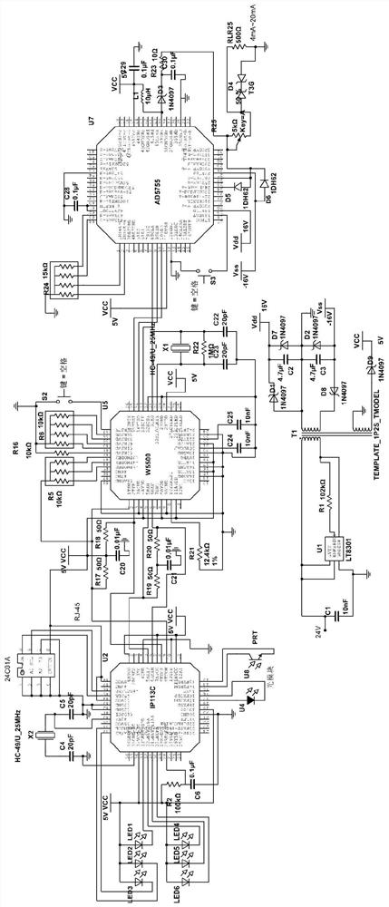
[0031] Embodiment 1: A system for remotely controlling actuators based on Ethernet network signals, see Figure 2 to Figure 4 .

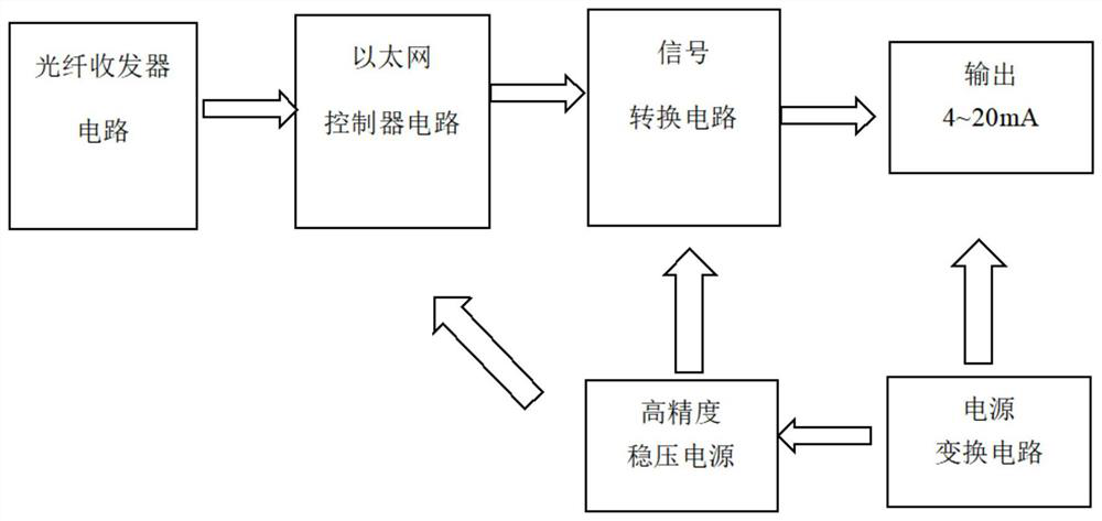
[0032] Such as figure 2 as shown, figure 2 The schematic diagram of the module circuit of the system is shown, and the system includes:

[0033] Fiber optic transceivers are used to connect with fiber optic circuits and receive fiber optic signals and connect to Ethernet to realize long-distance signal transmission;

[0034] An Ethernet controller is connected to the optical fiber transceiver and uses optical fiber signal information transmission with the optical fiber transceiver;

[0035] A signal conversion circuit is communicatively connected with the Ethernet controller and converts the network signal of the Ethernet controller into an analog signal output;

[0036] The analog output module circuit is connected with the signal conversion circuit and outputs a 4-20mA current signal.

[0037] In this system, the I / O line of each module of ...

Embodiment 2

[0060] Embodiment 2, a method for remotely controlling an actuator based on an Ethernet network signal, the method includes the following steps:

[0061] 1) The control signal is output to the fiber optic transceiver through Ethernet as a fiber optic signal;

[0062] 2) The optical fiber transceiver receives the optical fiber signal and converts the network signal into an analog current signal through the signal conversion circuit and outputs it to the actuator.

[0063] The method described in this embodiment is realized based on the system described in Embodiment 1. During implementation, the signal transmission mode between the system and the host computer is optical fiber transmission; the analog output circuit adopted by the module provides monitoring and control through the optical fiber network The function of input and output port control can use the network to pass through the current node, and use simple logic to control the node of the output port according to the i...


PUM


Abstract

The invention discloses a system and a method for remotely controlling an actuator based on network signals of Ethernet, and aims to solve the technical problems of low communication speed, requirement of paving of a large number of cables, signal attenuation and time delay of a traditional circuit. The system comprises an optical fiber transceiver connected with an optical fiber circuit and used for receiving optical fiber signals, an Ethernet controller connected with the optical fiber transceiver and in optical fiber signal information transmission with the optical fiber transceiver, and a signal conversion circuit in communication connection with the Ethernet controller and used for converting the network signal of the Ethernet controller into an analog signal to be output. The method comprises the following steps of: (1) outputting a control signal to an optical fiber transceiver in the form of an optical fiber signal through the Ethernet; and (2) enabling the optical fiber transceiver to receive the optical fiber signal, convert the network signal into an analog quantity current signal through a signal conversion circuit, and output the analog quantity current signal into an actuator. The system is strong in anti-interference capability, greatly reduces the usage amount of cables, and can save a large amount of construction cost and hardware cost.

Description

technical field [0001] The present invention relates to the technical field of industrial automation control, in particular to the technical field of remote control of field equipment, in particular to a system and method for remotely controlling actuators based on Ethernet network signals. Background technique [0002] The existing 4-20mA analog control signals are mainly sent by DCS or intelligent control instruments, and such instruments are mainly installed in the cabinet room, far away from the production site, and signal transmission requires many signal lines, and the distance is long, causing interference Unfavorable factors such as poor ability and difficult construction. [0003] see figure 1 , the existing analog control output signal is mainly to convert the control signal of DCS or intelligent instrument into a 4-20mA current signal, and connect it to the industrial field actuator through a cable. This kind of signal transmission requires many signal lines, po...

Claims


Application Information

Patent Timeline
IPC IPC(8): G05B19/418
CPCG05B19/41845G05B2219/33273Y02P90/02
Inventor 杨九亚
Owner 杨九亚
Features
  • R&D
  • Intellectual Property
  • Life Sciences
  • Materials
  • Tech Scout
  • Unparalleled Data Quality
  • Higher Quality Content
  • 60% Fewer Hallucinations
Learn More