Tool setting device and turning and milling composite machine tool comprising tool setting device

A technology of tool setting device and tool setting instrument, which is applied in the direction of feeding device, automatic control device, metal processing machinery parts, etc., can solve the problems of auxiliary time increase and low processing efficiency, so as to avoid pollution, improve processing efficiency, and travel path reasonable effect

Pending Publication Date: 2022-01-07
GUANGDONG ORIGINAL POINT INTELLIGENT TECH CO LTD
View PDF0 Cites 1 Cited by
  • Summary
  • Abstract
  • Description
  • Claims
  • Application Information

AI Technical Summary

Problems solved by technology

However, most of the existing tool setting instruments are fixed and exposed on the bed of the machine tool. In order not to be polluted by cutting fluid and chips, the tool setting instrument is installed very far away from the clamping spindle. The tool setting instrument is not located between the tool magazine and Between the clamping spindles, after the tool is changed, it is necessary to control the tool to move to the tool setting instrument for a long distance, which increases the auxiliary time and reduces the processing efficiency

Method used


Image

  • Tool setting device and turning and milling composite machine tool comprising tool setting device
  • Tool setting device and turning and milling composite machine tool comprising tool setting device
  • Tool setting device and turning and milling composite machine tool comprising tool setting device

Examples


Embodiment Construction

[0024] The present invention provides a tool setting device and a turn-milling machine tool including the tool setting device. In order to make the purpose, technical solution and effect of the present invention clearer and clearer, the present invention will be further described in detail below with reference to the accompanying drawings and examples. It should be understood that the specific embodiments described here are only used to explain the present invention, and are not intended to limit the protection scope of the present invention.

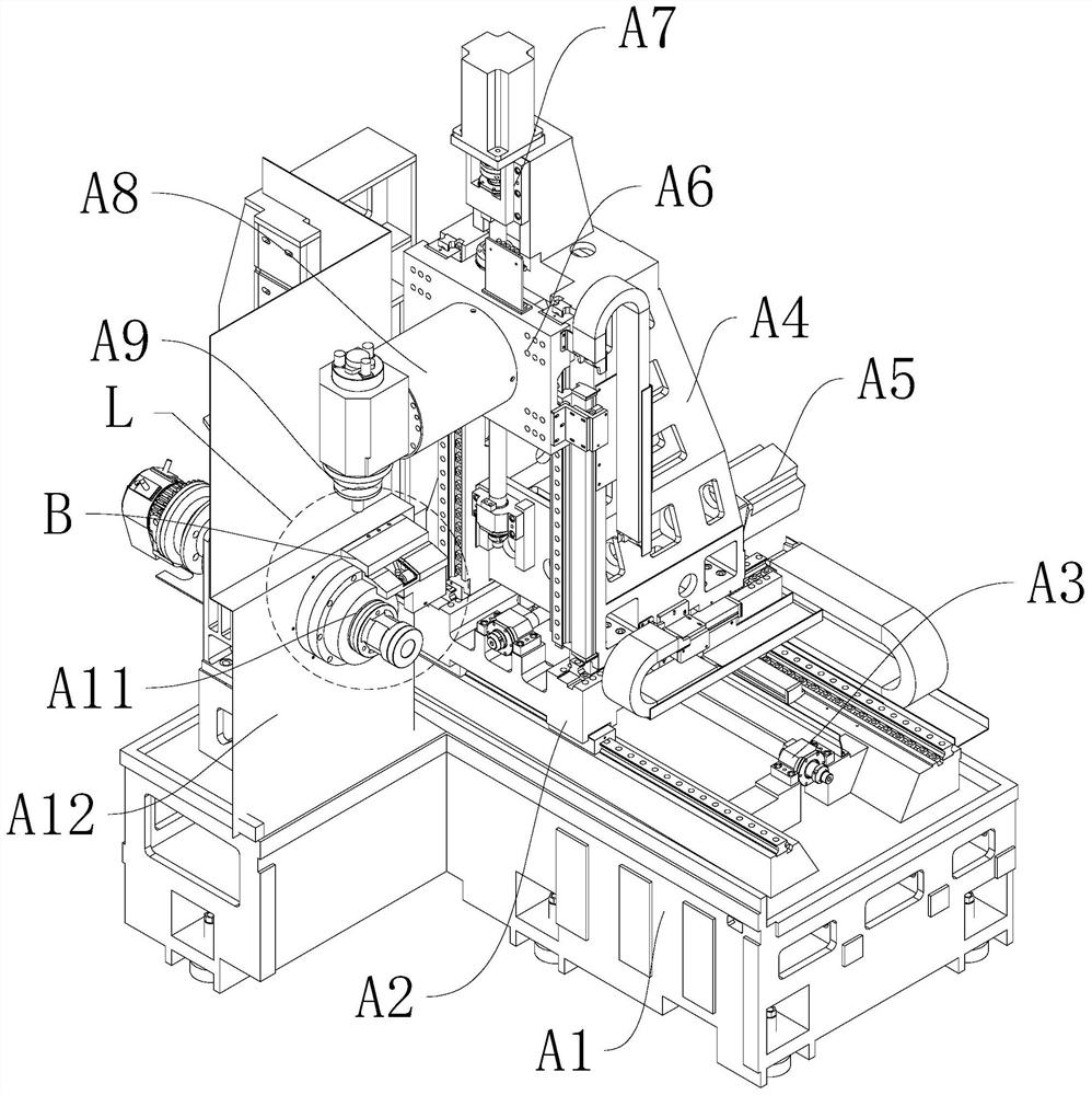
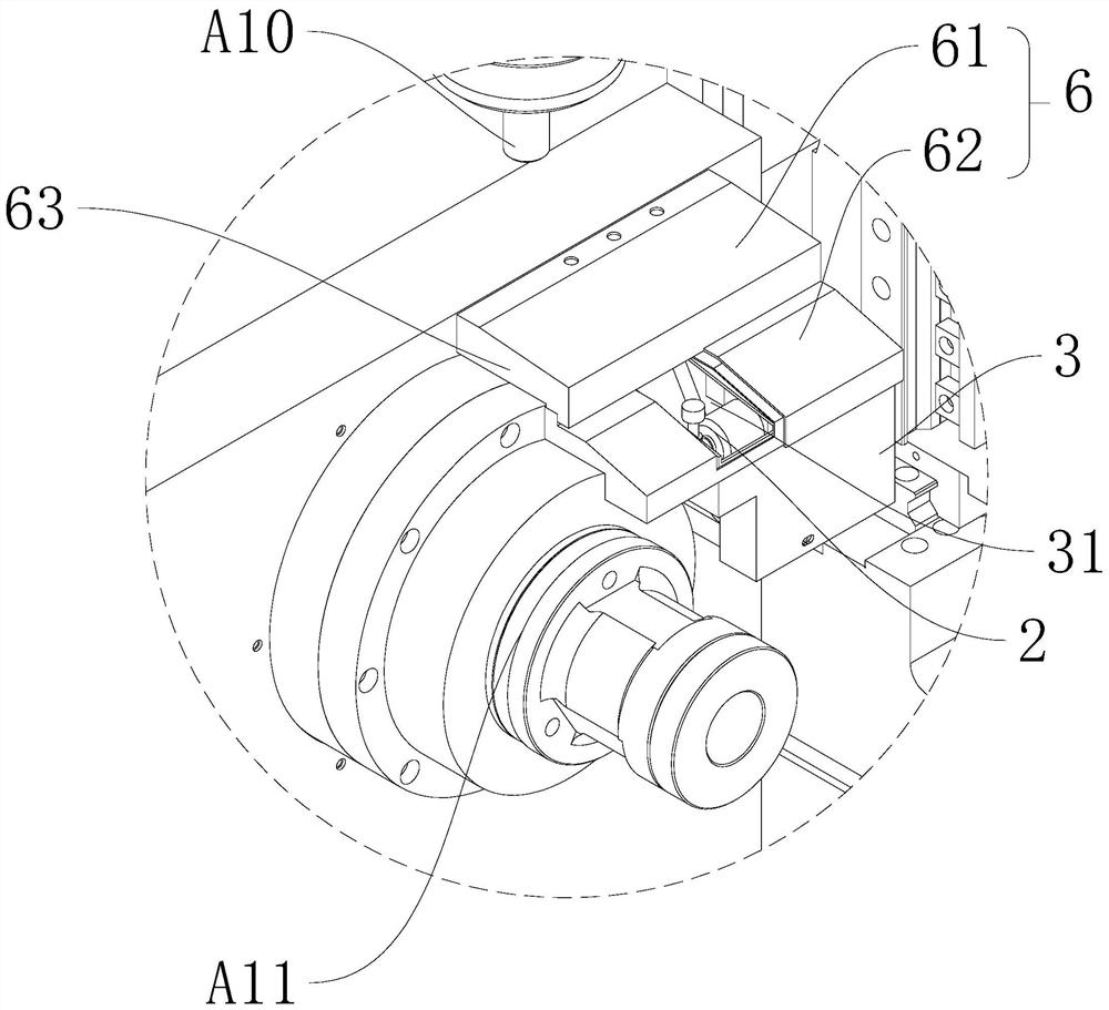
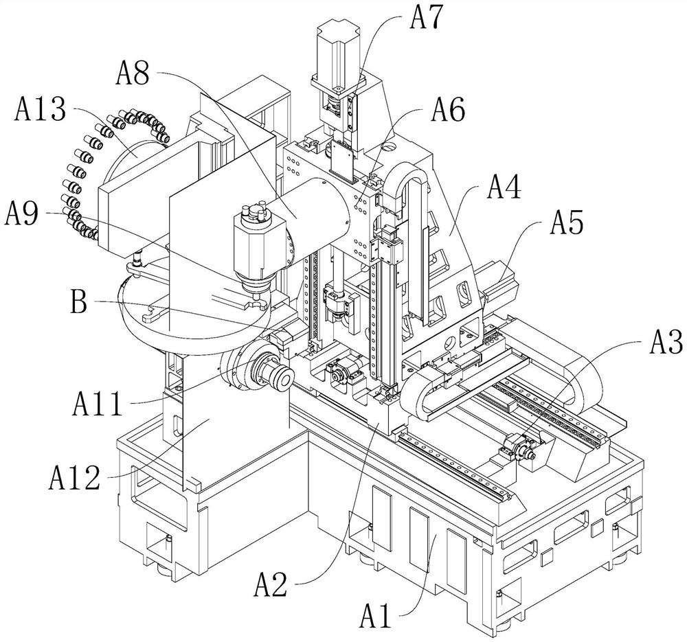
[0025] see Figure 1-Figure 5 , the present invention provides a tool setting device. The tool setting device is arranged on the side of the clamping spindle A11. The tool setting device includes a support 1, a tool setting instrument 2 arranged on the support 1, and a tool setting instrument 2 arranged outside the tool setting instrument 2. A protective cover 3, the top of the protective cover 3 is provided with an escape port 31 expos...


PUM


Abstract

The invention discloses a tool setting device and a turning and milling composite machine tool. The tool setting device is arranged beside a clamping main shaft, the tool setting device comprises a support, a tool setting gauge arranged on the support and a protective cover arranged outside the tool setting gauge, and the top of the protective cover is provided with an avoiding opening for exposing a contact of the tool setting gauge; and the protective cover is provided with a translation blocking cover and a driving device used for driving the translation blocking cover to close or open the avoiding opening, and the protective cover is provided with a fixed blocking cover used for shielding the driving device. The provided tool setting device is mounted beside the clamping main shaft, and the protective cover and the translation blocking cover perform all-directional covering protection on the tool setting gauge, so that the pollution of cuttings and cutting fluid to the contact of the tool setting gauge is avoided. After tool setting, the tool can quickly cut a workpiece located beside the tool setting device, the advancing path of the tool is reasonable, the moving time of the tool from tool changing to tool setting to the clamping spindle is greatly shortened, and the machining efficiency is improved.

Description

technical field [0001] The invention relates to the technical field of numerical control equipment, in particular to a tool setting device and a turning-milling compound machine tool including the tool setting device. Background technique [0002] The turning-milling compound machine tool is a five-axis linkage machine tool based on turning, supplemented by milling, boring, drilling and tapping. The turning and milling compound machine tool is equipped with a tool magazine and has the function of automatic tool change. It is a CNC machine tool that performs multi-process processing after one-time clamping of the workpiece. In the process of workpiece processing, auxiliary time such as workpiece loading and unloading and tool adjustment account for a considerable proportion of the processing cycle. The adjustment of the tool is time-consuming and laborious, and it is not easy to be accurate. Finally, trial cutting is required. Statistics show that the pure maneuvering time o...

Claims


Application Information

Patent Timeline
Patent Type & Authority Applications(China)
IPC IPC(8): B23Q15/22B23Q11/08B23P23/02
CPCB23Q15/22B23Q11/08B23P23/02
Inventor 张亮曾超峰刘志峰
Owner GUANGDONG ORIGINAL POINT INTELLIGENT TECH CO LTD
Why Eureka
Try Eureka