
Temperature-insensitive optical fiber optical grating stress sensor

A technology of stress sensor and optical fiber grating, which is applied in the direction of using optical devices to transmit sensing components, instruments, and measuring the force of changes in optical properties of materials when they are stressed, to achieve high sensitivity, shorten driving intervals, and low cost. Effect

Inactive Publication Date: 2008-07-16
BEIJING JIAOTONG UNIV
View PDF0 Cites 10 Cited by
  • Summary
  • Abstract
  • Description
  • Claims
  • Application Information

AI Technical Summary

Problems solved by technology

However, the method of realizing train positioning and real-time tracking with distributed fiber grating sensing that overcomes the cross-sensitivity of temperature stress has not yet been reported.

Method used


Image

  • Temperature-insensitive optical fiber optical grating stress sensor
  • Temperature-insensitive optical fiber optical grating stress sensor

Examples


Embodiment 1

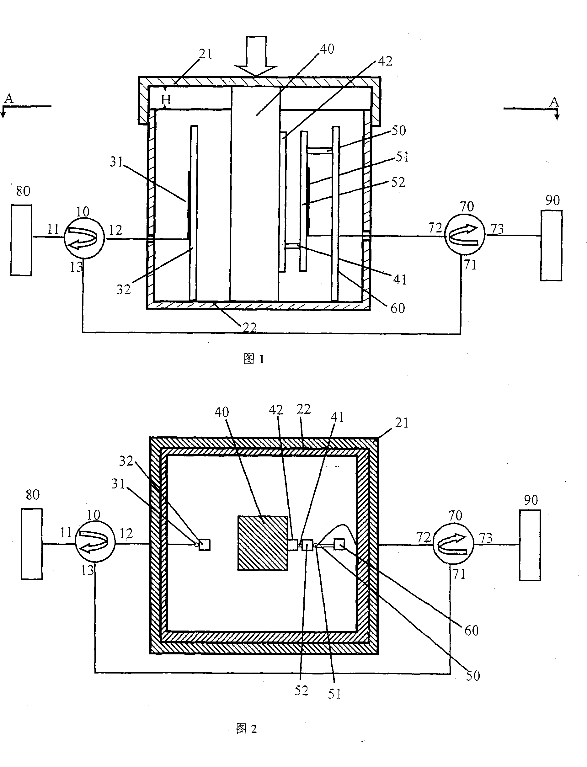
[0037] A temperature-insensitive fiber grating stress sensor, the connections between the components are as follows:

[0038] The cross-section of the sensor head structure main body 40 is a square with a side length of 2 cm and a length of 17 cm. It is made of phosphor copper material with very good stretchability. The bottom end is fixed on the bottom 22 of the package body, and the upper end is higher than the depth of the package body. 1cm, plus the cover 21 that can slide up and down to bear the external pressure.

[0039] Choose four phosphor bronze rods with a cross-section of very good elasticity as a square with a side length of 0.5 cm and a length of 15 cm, 14 cm, 14 cm, and 15 cm.

[0040] The first phosphor copper rod 32 and the fourth phosphor copper rod 60 are vertically fixed on the bottom 22 of the package;

[0041] The second phosphor copper rod 42 is vertically pasted on the sensor head structure main body 40;

[0042]The upper and lower ends of the third p...

Embodiment 2

[0049] A temperature-insensitive fiber grating stress sensor, the connections between the components are as follows:

[0050] The cross-section of the sensor head structure main body 40 is a circle with a diameter of 2 cm, and a spring 40 with a length of 20 cm is very flexible. In addition, the cover 21 that can slide up and down bears external pressure.

[0051] Choose a cylinder with a cross-sectional diameter of 0.5cm with very good elasticity, and four phosphor bronze rods with lengths of 17cm, 15cm, 15cm, and 17cm.

[0052] The first phosphor copper rod 32 and the fourth phosphor copper rod 60 are vertically fixed on the bottom 22 of the package;

[0053] The second phosphor copper rod 42 is vertically pasted on the sensor head structure main body 40;

[0054] The upper and lower ends of the third phosphor-bronze rod 52 are respectively connected to the upper end of the fourth phosphor-bronze rod 60 and the lower end of the second phosphor-bronze rod 42 through connect...


PUM

PropertyMeasurementUnit
wavelengthaaaaaaaaaa
lengthaaaaaaaaaa
wavelengthaaaaaaaaaa

Abstract

The invention discloses a fiber grating stress sensor which is not sensitive to temperature. A sensing head structure body (40), a first phosphor copper rod (32) and a fourth phosphor copper rod (60) are vertically fixed on the bottom part of a sealing body. The upper end surface of the sensing head structure body is contacted with the lower surface of a sliding cover (21). A second phosphor copper rod (42) is vertically stuck on the sensing head structure body (40). A third phosphor copper rod (52) is respectively connected with the fourth phosphor copper rod (60) and the second phosphor copper rod (42) by connecting pieces (50), (41). A measuring fiber raster (51) and a reference fiber grating (31) are respectively stuck on the third phosphor copper rod (52) and the first phosphor copper rod (32). The measuring fiber grating is connected with an optical power meter (90) through a right circulator. The reference fiber grating is connected with a broadband light source (80) through a left circulator. The sensor is not sensitive to temperature and is especially suitable for the running control of high-speed railway trains and the real-time tracing on trains.

Description

technical field [0001] The invention relates to a fiber grating stress sensor, which is suitable for stress and strain sensing of bridges, roads and building structures, and is especially suitable for high-speed railway train operation control and train real-time tracking. Background technique [0002] Pressure sensor is the most commonly used sensor in industrial practice. It is widely used in various industrial automatic control environments, involving water conservancy and hydropower, railway transportation, intelligent buildings, production automatic control, aerospace, military industry, petrochemical, oil wells, electric power, ships, machine tools , pipelines and many other industries, the current commonly used sensor principles and applications are as follows: [0003] Strain gauge pressure sensor: Resistance strain gauge is a sensitive device that converts the strain change on the measured piece into an electrical signal. It is one of the main components of piezore...

Claims


Application Information

Patent Timeline
Patent Type & Authority Applications(China)
IPC IPC(8): G01L1/24G01L19/04G01D5/353
Inventor 裴丽宁提纲童治刘艳谭中伟董小伟赵瑞峰祁春慧郭兰卓安生
Owner BEIJING JIAOTONG UNIV
Learn More