
Wire rod lifting appliance with magnetic attraction locking structure and applied to wire rod loading and unloading

A technology of locking structure and disc circle, applied in the direction of transportation and packaging, load hanging components, etc., can solve the problems of disc looseness, safety hazards, loading and unloading and falling off, and achieve the effect of stably supporting the disc circle

Pending Publication Date: 2022-01-07
ZHANJIANG PORT (GRP) CO LTD
View PDF2 Cites 0 Cited by
  • Summary
  • Abstract
  • Description
  • Claims
  • Application Information

AI Technical Summary

Problems solved by technology

[0007] The object of the present invention is to provide a kind of hoisting device with a magnetic locking structure that is applied to the hoop loading and unloading, so as to solve the problem that the hoisting gear currently on the market proposed by the above-mentioned background technology needs to pass the support arm during the process of loading and unloading the hoop. Supporting loading and unloading of the disk, there are certain safety hazards in the process of using the device, which may fall off during the loading and unloading process, and during the transfer process, due to the inertia of the disk itself, the disk may fall off. Looseness occurs, which prevents the convenience of transshipment

Method used


Image

  • Wire rod lifting appliance with magnetic attraction locking structure and applied to wire rod loading and unloading
  • Wire rod lifting appliance with magnetic attraction locking structure and applied to wire rod loading and unloading
  • Wire rod lifting appliance with magnetic attraction locking structure and applied to wire rod loading and unloading

Examples


Embodiment Construction

[0032] Next, the technical solutions in the embodiments of the present invention will be described in connection with the drawings of the embodiments of the present invention, and it is understood that the described embodiments are merely the embodiments of the present invention, not all of the embodiments. Based on the embodiments of the present invention, all other embodiments obtained by those of ordinary skill in the art are in the range of the present invention without making creative labor premise.

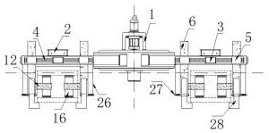
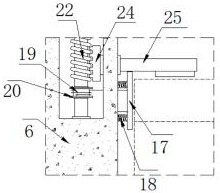
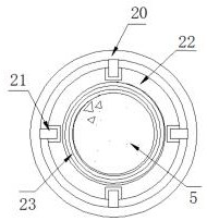
[0033] See Figure 1-8 The present invention provides a technical solution: A round plate is detachably applied to a locking structure having a magnetic circular disc spreader, comprising: a circular spreader disk body 1, the current direction control box 2, an electromagnet 3 fixed, the fixing screw 4, moving the electromagnet 5, the stopper plate 6 hanging, the pinion gear 7, the receiving groove 8, the stopper 9, the driven gear 10, the connecting rod 11, the stopper bar 12, t...


PUM


Abstract

The invention discloses a wire rod lifting appliance with a magnetic attraction locking structure and applied to wire rod loading and unloading. A wire rod lifting appliance main body serving as a lifting appliance device is mounted below a lifting arm through a specified chain, and a current direction control box for conveniently controlling the current direction is mounted at the top of the outer side of the wire rod lifting appliance main body; limiting lifting plates are arranged on the left side and the right side of one end of the wire rod lifting appliance main body; and the bottom of the current direction control box is connected with one end of a fixed electromagnet through a cable, one end of a driving gear is connected with a driven gear in a engaged mode, and the inner side of the driven gear is embedded in the outer side of a connecting rod. According to the wire rod lifting appliance with the magnetic attraction locking structure and applied to wire rod loading and unloading, the current direction control box is arranged, the connecting gear can drive an upper supporting tooth block and a lower supporting tooth block which are connected in a engaged mode on the two sides to move inside a limiting transverse rod, therefore the inner side of a wire rod can be conveniently limited and clamped, and the purpose of stably supporting the wire rod is achieved.

Description

Technical field [0001] The present invention relates to a disk-handling techniques, and in particular having a circular magnetic disk locking structure spreader disk circle detachably applied to one kind. Background technique [0002] When loading or unloading wharf, brigade selection process 10 bags bag spreader boom as the boom round disk, 10 bags of bag spreader boom total of five lugs, the total length is also suitable for crane unloading the reel circle 5 length; Thus, the 10 bags of bag spreader rope attachments and other working parts removed, the assembly work of the spreader disk circle fitting attachments (rope, chain or the like handling), it would be five standard derrick round spreader reel, but there are some disadvantages of the device: [0003] Publication No. CN203682898U discloses a steel pretreated with the circular spreader disk cartridge apparatus can be realized by rotating the rotation means, on the other hand by the stud threaded rod diameter enables high ...

Claims


Application Information

Patent Timeline
Patent Type & Authority Applications(China)
IPC IPC(8): B66C1/06
CPCB66C1/06
Inventor 苏开润崔骞骆国强张文鹰陈卫敖庆孙达勇
Owner ZHANJIANG PORT (GRP) CO LTD
Learn More