Combined cutter device of hydraulic cementing insulation clamping plate dismantling device

An insulating splint and combined technology, which is applied in the field of parts and components, can solve the problems of easy damage, high cost, and large loss, and achieve the effects of not easy to damage, good stress conditions, and cost saving

Pending Publication Date: 2022-01-07
上海瑞纽机械股份有限公司
View PDF0 Cites 0 Cited by
  • Summary
  • Abstract
  • Description
  • Claims
  • Application Information

AI Technical Summary

Problems solved by technology

See "TB / T 2975-2018 Rail Bonded Insulated Joints" for the technical requirements of on-site glued insulating joints. The glued insulating joint of m rail type is taken as an example. The longitudinal joint resistance is as high as 3000kN. It can be seen that a large mechanical force is required to remove the splint from the rail waist. The head of the long cutter is the direct actuator for removing the glued splint. It bears a lot of force, is easily damaged, has a short life, and needs to be replaced frequently. The handle of the long cutter is a part subject to compressive stress, which has good stress conditions and is not easy to be damaged. If it is replaced together with the cutter head as a whole, the cost will be high , the loss is also larger

Method used


Image

  • Combined cutter device of hydraulic cementing insulation clamping plate dismantling device
  • Combined cutter device of hydraulic cementing insulation clamping plate dismantling device
  • Combined cutter device of hydraulic cementing insulation clamping plate dismantling device

Examples


Embodiment Construction

[0026] In order to better understand the above technical solutions of the present invention, the technical solutions of the present invention will be further described below in conjunction with the accompanying drawings and examples.

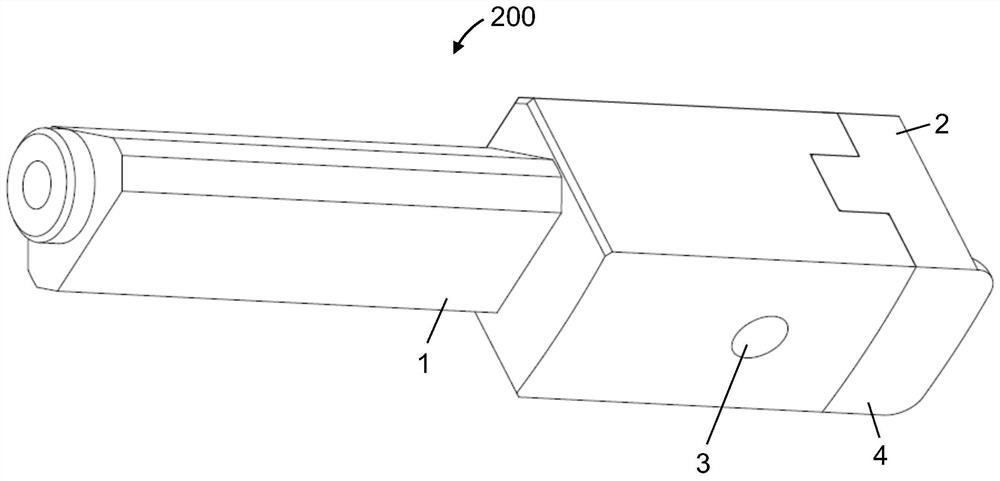
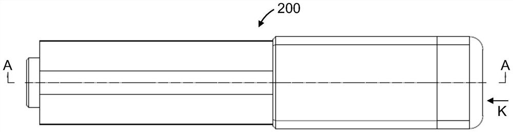
[0027] Combine figure 1 As shown, a combined cutter device of a hydraulic adhesive insulating splint removal device according to the present invention is provided on a main frame 100 of the hydraulic glue splint disassembly device, including two symmetrical setting of the cutter 200, can Better finished the work of the removal of the rubber splint.

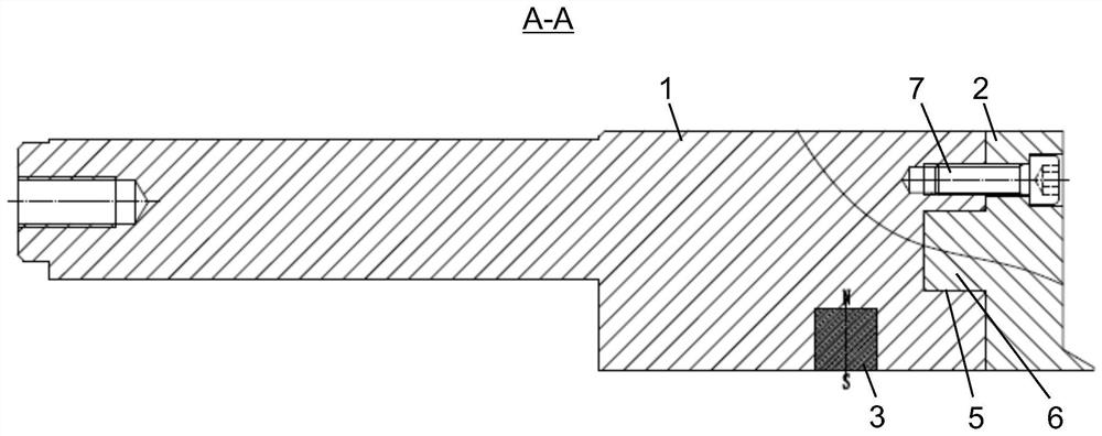
[0028] Each of the fixed cutters 200 includes a knife handle 1, a cutter head 2, and a magnet 3.

[0029] The rear end of the tool holder 1 is connected to the main frame 100 through the screw, and the front end is connected to the cutter head 2.

[0030] The working surface 4 of the cutter head 3 is disposed as a circular arc shape, and the arc radius is in line with the arc radius of the track.

[003...


PUM

PropertyMeasurementUnit
Diameteraaaaaaaaaa
Heightaaaaaaaaaa

Abstract

The invention discloses a combined cutter device of a hydraulic cementing insulation clamping plate dismounting device, which is arranged on a main frame of the hydraulic cementing insulation clamping plate dismounting device and comprises two fixed cutters which are symmetrically arranged; each fixed cutter comprises a cutter handle, a cutter head and a magnet; the rear end of the cutter handle is connected with the main frame, and the front end of the cutter handle is connected with the cutter head; the magnet is embedded in the side face, facing the rail web of the steel rail, of the cutter handle. The working surface of the cutter head is arc-shaped; the contact faces between the cutter handle and the cutter head are connected in the mode that the groove and the boss are embedded with each other. The device is used for dismounting the glue joint insulation clamping plate which fails on site.

Description

Technical field [0001] The present invention relates to a component of a hydraulic glue splint removal device, and more particularly to a combined cutter device for a hydraulic adhesive insulating pinch removal device. Background technique [0002] When the end of the insulating joint site on the early railway line suddenly breaks or discovers damage, it is generally used to insert a short track after the sawing, but the labor cost is high, and the cost of raw material is also high. As one of the three key parts of the railway line disease, the joint is placed in the working maintenance, especially the insulating joint portion, not only directly affects the lack of line smoothness, but also has a pivotal impact on the safety operation of the line safety. Therefore, in recent years, a glue splint vulcanized disassembly has been developed. It uses heating method to reduce the strength of the adhesive, which is easy to remove, but because there is a variety of disadvantages, the use...

Claims


Application Information

Patent Timeline
IPC IPC(8): E01B29/32B26D7/26
CPCE01B29/32B26D7/2614
Inventor 包园园杨建文
Owner 上海瑞纽机械股份有限公司
Why Eureka
Try Eureka