Supercritical reheating regenerative Rankine cycle system
A technology of regenerative system and circulation system, which is used in steam engine installations, steam applications, machines/engines, etc., to achieve the effect of improving circulation thermal efficiency, increasing endothermic temperature, and efficient utilization
- Summary
- Abstract
- Description
- Claims
- Application Information
AI Technical Summary
Problems solved by technology
Method used
Image

Examples
Embodiment 1
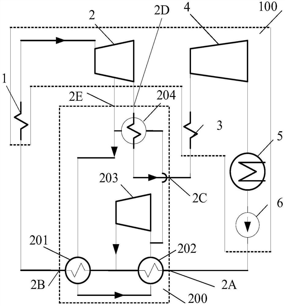
[0038] When Example 1 works,
[0039] In the supercritical heat recovery system 200, the low-pressure high-temperature steam entering from the low-pressure high-temperature steam inlet 2E of the heat recovery system is divided into the first heat recovery and the second heat recovery in proportion, and the second heat recovery enters the third high-temperature heat recovery The high-temperature steam inlet of the high-temperature regenerator 204 releases heat. After the first regenerating heat enters the high-temperature steam inlet of the first high-temperature regenerator 201 to release heat, it then enters the high-temperature steam inlet of the second high-temperature regenerator 202 to release heat, and then with the third high-temperature regenerator. The high-temperature steam from the high-temperature steam outlet of the regenerator 204 merges and enters the first compressor 203 to perform work;
[0040] The low-temperature working medium (low-temperature water) enteri...
Embodiment 2
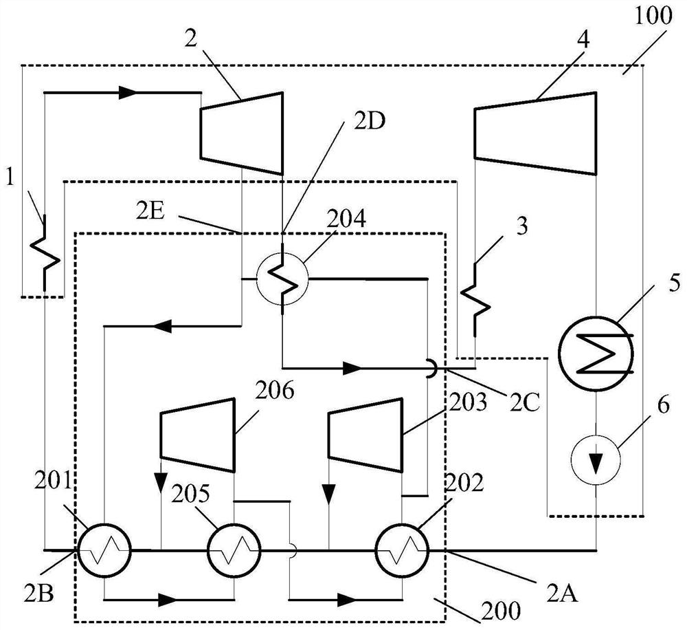
[0047] When Example 2 works,
[0048] In the supercritical recuperation system 200:
[0049] The first regenerative heat entering from the low-pressure high-temperature steam inlet 2E of the regenerative system enters the high-temperature steam inlet of the first high-temperature regenerator 201, the high-temperature steam inlet of the fourth high-temperature regenerator 205, and the high-temperature steam of the second high-temperature heat exchanger 202 in sequence. After the steam inlet releases heat, it merges with the high-temperature steam at the high-temperature steam outlet of the third high-temperature regenerator 204 and enters the first compressor 203 to perform work;
[0050] The low-temperature working fluid (low-temperature water) entering from the low-temperature water inlet 2A of the recuperation system of the supercritical recuperation system 200 (the low-temperature water inlet of the second high-temperature regenerator 202 ) passes through the second high-te...
Embodiment 3
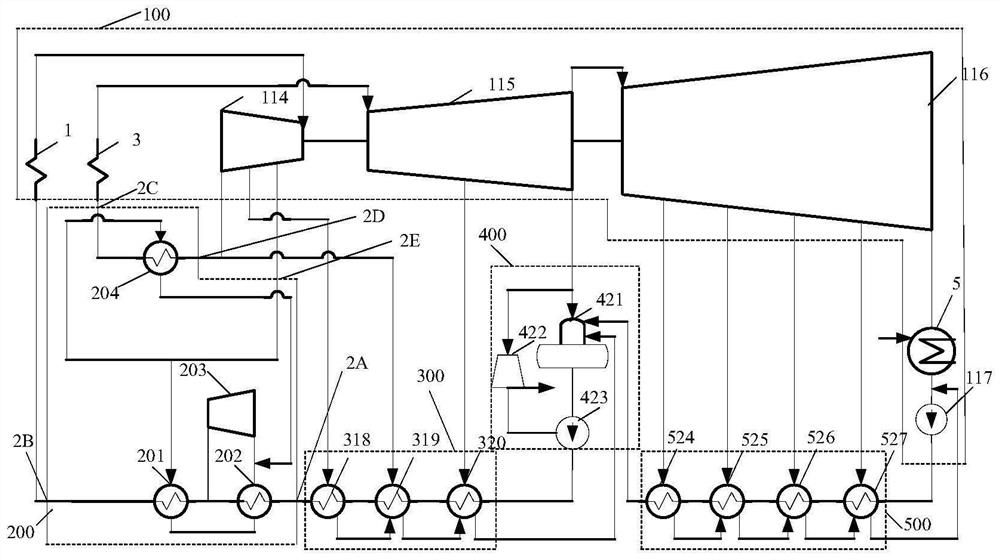
[0066] When working in Example 3,
[0067] In the supercritical recuperation system 200:
[0068] The low-pressure, high-temperature steam that enters from the low-pressure, high-temperature steam inlet 2E of the recuperation system is proportionally divided into two paths, the first regenerative and the second regenerative, wherein the second regenerative enters the high-temperature steam inlet of the third high-temperature regenerator 204 to release heat. After the first regenerative heat enters the high-temperature steam inlet of the first high-temperature regenerator 201 to release heat, it then enters the high-temperature steam inlet of the second high-temperature regenerator 202 to release heat, and then with the high-temperature steam at the high-temperature steam outlet of the third high-temperature regenerator 204 The steam merges and enters the first compressor 203 to do work;
[0069] The low-temperature working medium (low-temperature water) entering from the low-...
PUM
 Abstract
Description
Claims
Application Information
 - R&D
- Intellectual Property
- Life Sciences
- Materials
- Tech Scout
- Unparalleled Data Quality
- Higher Quality Content
- 60% Fewer Hallucinations
Browse by: Latest US Patents, China's latest patents, Technical Efficacy Thesaurus, Application Domain, Technology Topic, Popular Technical Reports.
© 2025 PatSnap. All rights reserved.Legal|Privacy policy|Modern Slavery Act Transparency Statement|Sitemap|About US| Contact US: help@patsnap.com