Pressurizing gas distribution mechanism of annular tandem straight-cylinder engine, and annular straight-cylinder engine

A valve train, engine technology, applied in engine components, combustion engines, machines/engines, etc., can solve problems affecting engine power density and maximum output power, increased weight, and insufficient exhaust.

Pending Publication Date: 2022-01-07
NAT UNIV OF DEFENSE TECH
View PDF1 Cites 0 Cited by
  • Summary
  • Abstract
  • Description
  • Claims
  • Application Information

AI Technical Summary

Problems solved by technology

[0006] 1. The air flow needs to pass through multiple contact surfaces, and there are many contact surfaces that need to be sealed, which not only leads to high manufacturing costs but also easily causes the problem of seal leakage
[0007] 2. A long gas distribution process will cause insufficient exhaust (that is, there is residual exhaust gas in the long gas distribution channel), which will affect the power density and maximum output power of the engine
[0008] 3. Due to the setting of the second air port, the second air channel and the third air port on the main rotor, the structural strength of the main rotor will be reduced, and in order to ensure the structural strength of the main rotor, the size of the main rotor needs to be thickened ( increase in size and weight), which makes it impossible to meet the special requirements for high performance and light weight in some usage scenarios (such as small unmanned platforms), and the thickening of the main rotor will also lead to large inertial force, which further limits the Application Scenarios of Toroidal Tandem Straight Cylinder Engine

Method used


Image

  • Pressurizing gas distribution mechanism of annular tandem straight-cylinder engine, and annular straight-cylinder engine
  • Pressurizing gas distribution mechanism of annular tandem straight-cylinder engine, and annular straight-cylinder engine
  • Pressurizing gas distribution mechanism of annular tandem straight-cylinder engine, and annular straight-cylinder engine

Examples


Embodiment Construction

[0037] The present invention will be further described below in conjunction with the embodiments, and the described embodiments are only a part of the embodiments of the present invention, not all of them. Based on the embodiments of the present invention, other used embodiments obtained by persons of ordinary skill in the art without creative efforts all belong to the protection scope of the present invention.

[0038] In the description of the present invention, it should be noted that the terms "center", "upper", "lower", "left", "right", "vertical", "horizontal", "inner", "outer" etc. The indicated orientation or positional relationship is based on the orientation or positional relationship shown in the drawings, and is only for the convenience of describing the present invention and simplifying the description, rather than indicating or implying that the referred device or element must have a specific orientation, or in a specific orientation. construction and operation, ...


PUM


Abstract

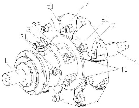
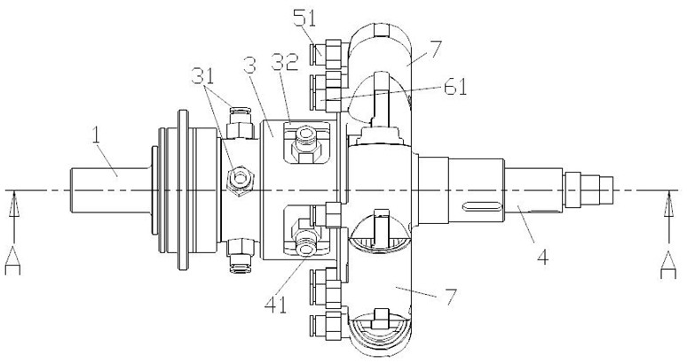
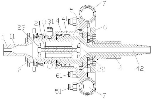
The invention belongs to the technical field of annular engines, discloses a pressurizing gas distribution mechanism of an annular tandem straight-cylinder engine, and the annular straight-cylinder engine, and aims to solve the problems that an existing annular engine is poor in sealing performance and cannot be used under the conditions of high performance and light weight. The pressurizing gas distribution mechanism of the annular tandem straight-cylinder engine comprises a gas inlet shaft with a gas inlet channel, wherein the gas inlet shaft is coaxially and fixedly connected with a central gas distribution shaft, the periphery of the central gas distribution shaft is sequentially and rotationally connected with a first rotor gas distribution shaft and a second rotor gas distribution shaft in the axial direction of the central gas distribution shaft, and the central gas distribution shaft comprises a connecting flange used for being connected with the gas inlet shaft; and the connecting flange is connected with a barrel body, a plurality of gas inlet ports are formed in the side, facing the connecting flange, of the barrel body in the radial direction of the barrel body, and each gas inlet port communicates with the gas inlet channel.

Description

technical field [0001] The invention belongs to the technical field of piston engines, and in particular relates to a booster gas distribution mechanism of an annular series straight-cylinder engine and the annular straight-cylinder engine, which are used to distribute air to the piston engine. Background technique [0002] The reciprocating piston engine has a simple principle and mature technology, and is widely used in various fields. However, due to the characteristics of the reciprocating motion of the piston and the characteristics of the traditional crank-and-rod mechanism, it is difficult for the traditional reciprocating piston engine to significantly increase the power density and maximum output power. In order to improve the engine Power density and maximum output power, a feasible method is to arrange multiple cylindrical cylinders arranged in parallel along the same circumferential direction in series, and realize the reciprocating motion of the piston relative t...

Claims


Application Information

Patent Timeline
Patent Type & Authority Applications(China)
IPC IPC(8): F02B75/18F02B75/40F02B37/00F02M35/10F02M35/104
CPCF02B75/18F02B75/40F02B37/00F02M35/10091F02M35/10157F02M35/104Y02T10/12
Inventor 杨聪楠徐海军唐源江孙承亮高雪张国卿徐藜洋徐小军
Owner NAT UNIV OF DEFENSE TECH
Why Eureka
Try Eureka