Flood three-dimensional dynamic evolution and rendering method and device and electronic equipment

A three-dimensional dynamic and flooding technology, which is applied in filling planes with attributes, image data processing, 3D image processing, etc., can solve the problems of rough display effect and achieve the effect of optimized display effect

Pending Publication Date: 2022-01-07
宁波市水利水电规划设计研究院有限公司
View PDF0 Cites 2 Cited by
  • Summary
  • Abstract
  • Description
  • Claims
  • Application Information

AI Technical Summary

Problems solved by technology

[0003] In view of the above technical problems, the purpose of the present invention is to provide a flood three-dimensional dynamic evolution and rendering method, device and electronic equipment, to solve the problem of rough display effect of the traditional three-dimensional visualization display method in displaying flood evolution

Method used


Image

  • Flood three-dimensional dynamic evolution and rendering method and device and electronic equipment
  • Flood three-dimensional dynamic evolution and rendering method and device and electronic equipment
  • Flood three-dimensional dynamic evolution and rendering method and device and electronic equipment

Examples


Embodiment 1

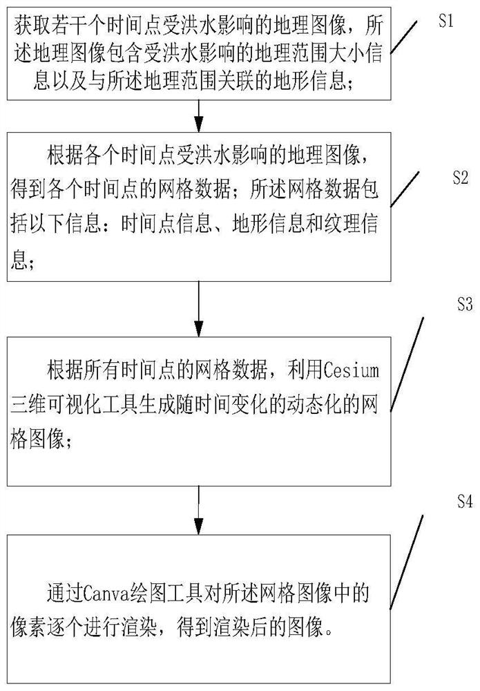
[0042] Please refer to figure 1 , which shows a flood three-dimensional dynamic evolution and rendering method according to an embodiment of the present invention, including the following steps:

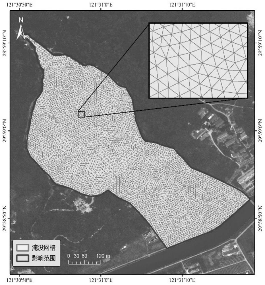
[0043] Step S1: Obtain geographic images affected by floods at several time points, the geographic images comprising size information of geographic ranges affected by floods and terrain information associated with the geographic ranges;

[0044] Among them, the geographical image is generally a vector map, and the geographic images affected by floods can be obtained from the runoff area information on the website of the hydrometeorological station. During the rainfall process, the area where runoff is generated on the watershed is called the runoff area, and its area is called the runoff area; the runoff area of ​​the watershed changes with the rainfall process. Specifically, the watershed flow can be quantified through the deployed hydrometeorological station network observe.

[0...

Embodiment 2

[0089] A flood three-dimensional dynamic evolution and rendering device of the present invention includes:

[0090] a geographic image acquisition module, configured to acquire geographic images affected by floods at several time points, the geographic images including size information of geographic areas affected by floods and terrain information associated with the geographic areas;

[0091] The grid data generation module is used to obtain grid data of each time point according to the geographical images affected by the flood at each time point; the grid data includes the following information: time point information, terrain information and texture information;

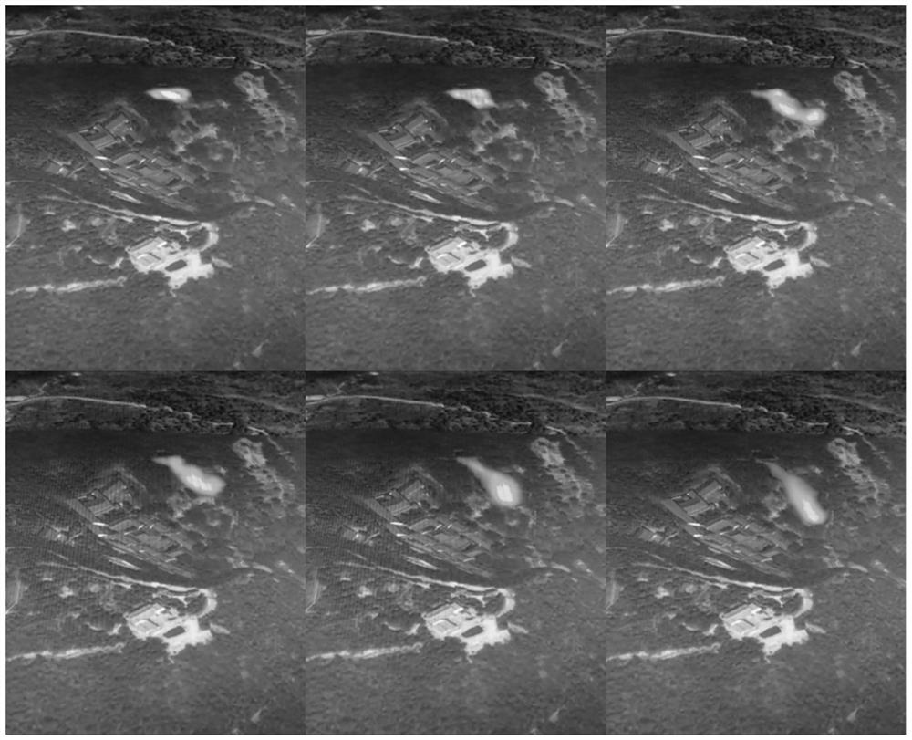
[0092] The dynamic image generation module is used to generate dynamic grid images that change with time using the Cesium 3D visualization tool according to the grid data at all time points;

[0093] The rendering module is used for rendering the pixels in the grid image one by one through the Canva drawing tool t...

Embodiment 3

[0098] Figure 4 A schematic structural diagram of an electronic device provided in the embodiment of this application, in this application, can be Figure 4 The schematic diagram shown is used to describe the electronic device 100 for implementing a flood 3D dynamic evolution and rendering method of the present invention according to the embodiment of the present application.

[0099] like Figure 4 Shown is a schematic structural diagram of an electronic device. The electronic device 100 includes one or more processors 102 and one or more storage devices 104. These components are interconnected through a bus system and / or other forms of connection mechanisms (not shown). even. It should be noted that Figure 4 The illustrated components and structures of the electronic device 100 are only exemplary and not limiting, and the electronic device may have Figure 4 shown in some components, which can also have image 3 Other components and structures not shown.

[0100]The ...


PUM


Abstract

The invention discloses a flood three-dimensional dynamic evolution and rendering method, a flood three-dimensional dynamic evolution and rendering device and electronic equipment. The flood three-dimensional dynamic evolution and rendering method comprises the following steps: acquiring geographic images influenced by flood at a plurality of time points; obtaining grid data of each time point according to the geographic image of each time point influenced by the flood; according to the grid data of all the time points, utilizing a Cesium three-dimensional visualization tool to generate a dynamic grid image changing along with time; and rendering pixels in the grid image one by one through a Canva drawing tool to obtain a rendered image. According to the method, three-dimensional dynamic evolution and rendering of flood routing are carried out by utilizing a Cesium three-dimensional visualization tool and combining a Canvas drawing technology newly added to HTML5, the flood routing process can be visually, three-dimensionally and vividly expressed, and the display effect can be optimized to the maximum extent.

Description

technical field [0001] The invention relates to the technical field of flood evolution visualization, in particular to a flood three-dimensional dynamic evolution and rendering method, device and electronic equipment. Background technique [0002] Numerical simulation and visualization research on flood evolution can visualize and comprehensively understand the occurrence and development process and status of floods, as well as the submerged range and impact degree, etc., and effectively provide relevant decision-making basis for flood disaster emergency management and disaster prevention and control. Compared with the three-dimensional three-dimensional scene, the plane expression of the numerical simulation results cannot show the flood evolution scene more vividly and intuitively than the three-dimensional three-dimensional scene. The difficulty of numerical simulation of 3D visualization lies in the processing of huge data volumes of terrain and images. Many studies only...

Claims


Application Information

Patent Timeline
Patent Type & Authority Applications(China)
IPC IPC(8): G06T11/40G06T15/00G06T17/20
CPCG06T11/40G06T15/005G06T17/205
Inventor 顾巍巍张卫国范仲丽江雨田张焱张嫣然杨珍朱从飞赵思远黄佳杰徐金柳陈龙赞沈日新查显能孙巍王晓晓孙飞飞
Owner 宁波市水利水电规划设计研究院有限公司
Why Eureka
Try Eureka