Graphite electrode automatic detection and packaging device

An automatic detection, graphite electrode technology, applied in packaging, packaging protection, transportation and packaging, etc., can solve the problems of inconvenient measurement and transportation, potential safety hazards, cumbersome measurement steps, etc., to improve the degree of automation and operation efficiency, improve adaptability Sex, reduce the effect of manual labor

Pending Publication Date: 2022-01-11
河南幔利橡树自动化科技技术有限公司
View PDF0 Cites 0 Cited by
  • Summary
  • Abstract
  • Description
  • Claims
  • Application Information

AI Technical Summary

Problems solved by technology

[0003] When measuring the density of graphite electrodes, the "immersion method" is often used to measure the density, and the measurement steps are cumbersome; and when measuring the resistance, due to the large electrode rod body, it is inconvenient to move and transport the measurement, and the safety hazard is also relatively large

Method used


Image

  • Graphite electrode automatic detection and packaging device
  • Graphite electrode automatic detection and packaging device
  • Graphite electrode automatic detection and packaging device

Examples


Embodiment 1

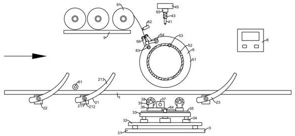
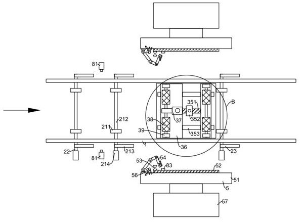
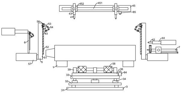
[0034] like Figure 1-Figure 9As shown, the graphite electrode automatic detection packaging device includes a feeding guide rail 1, a bottom support mechanism 3, a PLC controller 8, a first laser range finder 81, a second laser range finder 82 and a third laser range finder 83; In the material conveying direction, the feeding guide rail 1 is set, the bottom supporting mechanism 3 is set under the feeding guiding rail 1, and the first stopper 21 is set at the feeding end of the bottom supporting mechanism 3; the bottom supporting mechanism 3 includes a weighing platform 31, a second Two loading plates 32, the third loading plate 33, the second lifter 34, the third driving motor 37, idlers 38 and the second fixed rod 39; the second loading plate 32 is set above the weighing platform 31, and the second loading A second lifting member 34 is arranged on the plate 32, and the second lifting member 34 is arranged in the vertical direction. A third bearing plate 33 is arranged above ...

Embodiment 2

[0039] like Figure 1-Figure 9 As shown, for the above embodiments, this embodiment optimizes the structure of the guide rail.

[0040] In the present graphite electrode automatic detection packaging device, the feeding guide rail 1 is arranged obliquely downward along the material conveying direction. The inclined downward feeding guide rail 1 facilitates the forward movement of the electrode rod body through the effect of its own gravity, and there is no need to provide a conveying power mechanism, which saves costs.

Embodiment 3

[0042] like Figure 1-Figure 9 As shown, for the above embodiments, this embodiment optimizes the limiting structure.

[0043] In the graphite electrode automatic detection packaging device, a first limiter 21 and a third limiter 23 are respectively set at the feed end and the discharge end of the bottom support mechanism 3, and the first limiter 21 and the third limiter The bit parts 23 are respectively electrically connected to the output control terminals of the PLC controller 8 . During the initial work, the first limiter 21 is in a raised state. When the electrode rod body moves to the first limiter 21, the first limiter 21 limits the electrode rod and suspends the movement; when the bottom supporting mechanism 3 is in the In the "no-load" state, the third limiter 23 is in a raised state, the first limiter 21 slowly descends, the electrode rod slowly rolls to the third limiter 23, and then the first limiter 21 is lifted again, The bottom supporting mechanism 3 then lift...


PUM


Abstract

The invention relates to the field of carbon preparation, in particular to a graphite electrode automatic detection and packaging device which comprises a feeding guide rail, a bottom support mechanism, a PLC, first laser range finders, a second laser range finder and a third laser range finder. The feeding guide rail is arranged in the material conveying direction, the bottom support mechanism is arranged below the feeding guide rail, and a first limiting piece is arranged at the feeding end of the bottom support mechanism. The first laser range finders are arranged on the two sides of the feeding guide rail correspondingly, and the detection ends of the two first laser range finders are oppositely arranged. The second laser range finder is arranged on a third bearing plate, a third laser range finder is arranged above the second laser range finder, and the detection end of the third laser range finder is vertically arranged downwards. By means of the device, density and resistance measurement can be conveniently and continuously carried out on an electrode bar body, laser marking and automatic straw rope winding packaging operation can be achieved, and the automation degree and the operation efficiency of the operation are greatly improved.

Description

technical field [0001] The invention relates to the field of carbon electrode preparation, in particular to the technical field of the structure of a graphite electrode automatic detection and packaging device. Background technique [0002] In the process of making carbon graphite electrode rods, it is necessary to detect the density, resistance, diameter, length, weight and other indicators of the product to ensure the quality, and to protect the electrode rods by wrapping grass ropes to reduce the risk of damage during transportation. damage. [0003] When measuring the density of graphite electrodes, the "immersion method" is often used to measure the density, and the measurement steps are cumbersome; and when measuring the resistance, due to the large electrode rod body, the measurement is inconvenient to move and transport, and the safety hazard is also relatively large. Contents of the invention [0004] The purpose of the present invention is to provide an automati...

Claims


Application Information

Patent Timeline
Patent Type & Authority Applications(China)
IPC IPC(8): B65B57/10B65B19/34B65B35/22B65B11/04B65B61/06B65B63/00
CPCB65B57/10B65B19/34B65B35/22B65B11/04B65B61/06B65B63/005
Inventor 王树涛邓林云王东亮
Owner 河南幔利橡树自动化科技技术有限公司
Why Eureka
Try Eureka