
Heading machine and unilateral gripper shoe device thereof

A technology of roadheader and shoe plate, applied in mining equipment, earth-moving mining, tunnels, etc., can solve the problem of auxiliary support shoes occupying installation space and other problems, and achieve the effect of small occupied space and space saving

Pending Publication Date: 2022-01-11
CHINA RAILWAY ENGINEERING EQUIPMENT GROUP CO LTD
View PDF2 Cites 0 Cited by
  • Summary
  • Abstract
  • Description
  • Claims
  • Application Information

AI Technical Summary

Problems solved by technology

[0005] The purpose of the present invention is to provide a single-side support shoe device for a roadheader to solve the problem that in the prior art, the auxiliary support shoe with an additional support reaction force on the main beam is directly fixed on the main beam, causing the auxiliary support shoe to be occupied when the auxiliary support shoe is not working. Technical issues of installation space

Method used


Image

  • Heading machine and unilateral gripper shoe device thereof
  • Heading machine and unilateral gripper shoe device thereof
  • Heading machine and unilateral gripper shoe device thereof

Examples


specific Embodiment 1

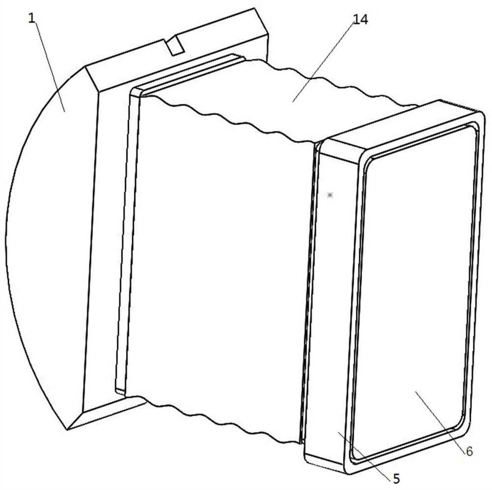
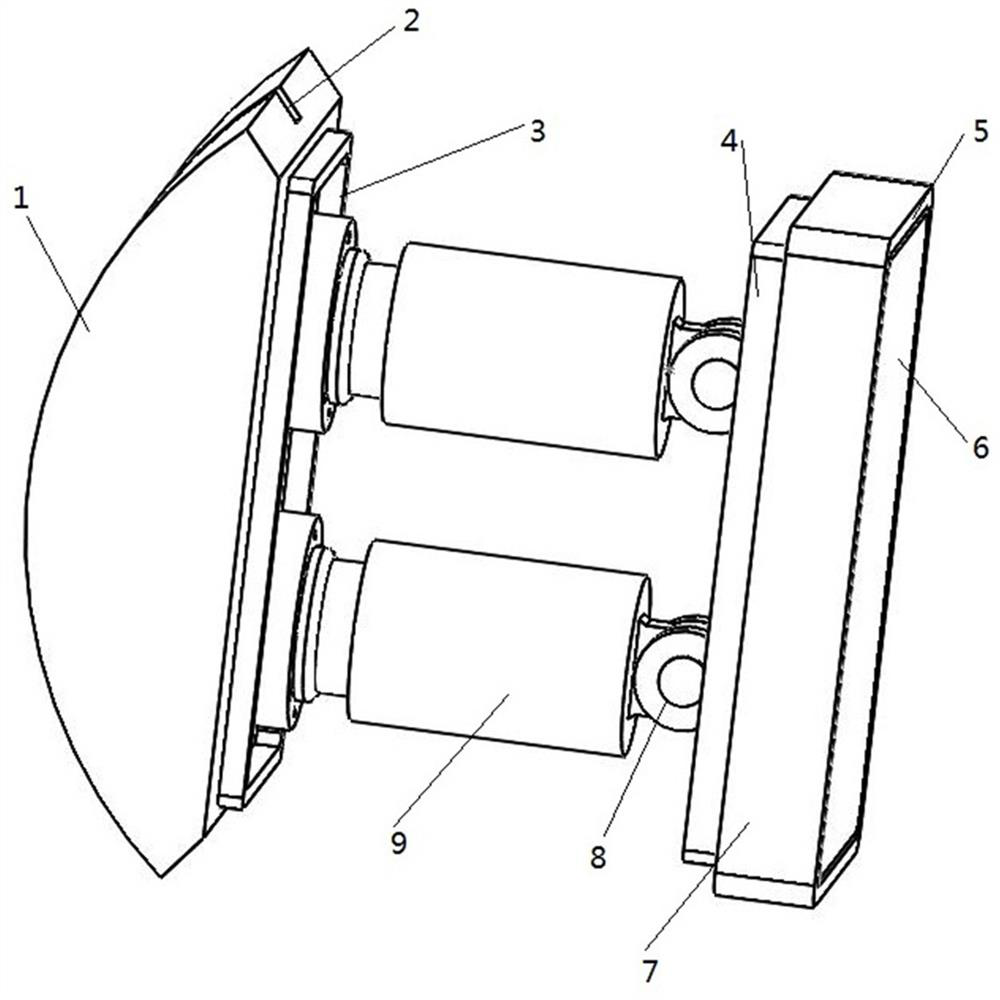
[0074] The roadheader provided in this embodiment is a hard rock roadheader. The difference between it and the hard rock roadheader in the prior art is that it is additionally equipped with a mobile spreader shoe unit, which includes two single-side braces. Shoe device, two unilateral support shoe devices can be symmetrically installed on both sides of the main body of the roadheader, which can form a temporary support and provide support and reaction force. When the main support shoe on the hard rock roadheader is sufficient to provide support and reaction force, the mobile support shoe unit can be directly removed to save corresponding space.

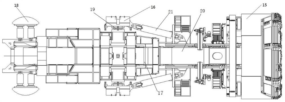
[0075] Such as Figure 1 to Figure 4 As shown, the hard rock roadheader in this embodiment specifically includes a roadheader main body 17, and the roadheader body 17 includes a main beam 20, a front shield body 15 is arranged at the front end of the main beam 20, a cutter head is arranged on the front shield body 15, and a 20 is pro...

specific Embodiment 2

[0096] The main difference between it and Embodiment 1 is that in Embodiment 1, the telescopic driving structure adopts superconducting electromagnets to drive the shoe to extend outward. In this embodiment, the telescoping drive structure can directly use a hydraulic cylinder, and the hydraulic cylinder can be used on the existing roadheader corresponding to the main spreader cylinder, and it is necessary to pay attention to the corresponding configuration of the hydraulic oil circuit. When a hydraulic cylinder is used, the hydraulic cylinder can be directly used to drive the telescopic movement of the shoe plate.

specific Embodiment 3

[0098] The main difference between it and Embodiment 1 is that in Embodiment 1, the detachable connection structure on the connection base is a fixed electromagnet, which is energized and fixed on the main beam by adsorption. In this embodiment, the detachable connection structure on the connection seat is a connection plate, and the connection plate is provided with a bolt connection structure for detachable connection with the main beam. Due to the large number of installation bolts, this bolt installation method relatively low efficiency.


PUM


Abstract

The invention relates to a heading machine and a unilateral gripper shoe device thereof. The unilateral gripper shoe device comprises a connecting seat and a shoe plate. The inner side of the connecting seat is provided with detachable connecting structures which are used for being detachably and fixedly mounted on one side of a heading machine main body in the horizontal transverse direction; and the shoe plate is mounted on the outer side of the connecting seat in a guiding and telescopic mode through telescopic driving structures in the inside and outside direction, and a telescopic driving structure is used for driving the shoe plate to extend outwards so as to be supported on a tunnel hole wall and driving the shoe plate to retract inwards so as to leave the tunnel hole wall. The detachable connecting structures are arranged on unilateral gripper shoe devices and used for being temporarily mounted on one side of the heading machine main body according to actual needs, the unilateral gripper shoe devices are arranged in pairs so as to form a movable gripper shoe unit, when bearing reaction needs to be increased, the unilateral gripper shoe devices can be temporarily added, and the shoe plate is driven by the telescopic driving structures to extend outwards so as to increase the bearing reaction. According to the heading machine and the unilateral gripper shoe device thereof, in daily tunneling work, if not needed, the unilateral gripper shoe device can be detached, and space is saved.

Description

technical field [0001] The invention belongs to the technical field of excavation, and in particular relates to an excavation machine and a single-side support shoe device thereof. Background technique [0002] The structure of existing roadheader is the tunnel boring machine disclosed in the Chinese invention patent application of CN106285703B as authorized announcement number, comprises main girder, and saddle frame is arranged on the main beam, and foundation support shoe is installed on the saddle frame, and foundation support shoe is driven by oil cylinder Action, during the tunneling process of the roadheader, the support shoes on both sides provide the support and reaction force for the whole machine to advance forward. After the support shoes are supported by the oil cylinder against the hole wall, the oil cylinder continues to increase the thrust, and the friction generated by the hole wall acts as The driving force of the complete machine drives forward. Under som...

Claims


Application Information

Patent Timeline
IPC IPC(8): E21D9/10
CPCE21D9/1093
Inventor 李建斌朱英曹宸旭周坤石成虎
Owner CHINA RAILWAY ENGINEERING EQUIPMENT GROUP CO LTD
Learn More