
Eureka
For R&D, Eureka makes reading and utilizing patents & technical documents easy.
Eureka AIR
Designed for self-driven R&D workflows. Generate viable solutions, solve complex R&D challenges, empower your innovation with AI.

Eureka Materials
Designed for material experts only. Revolutionize your material R&D, from search, analyze, to developing new materials.

TechResearch
Generate reliable direction feasibility study reports for your R&D in just a few steps.

TechSeek
Discover and master advanced knowledge NOW. Basics, ideas, possibilities, all at once.

TechMind
As an expert in R&D Theories, TechMind can generates customized viable solutions instantly.

TechRisk
Analyze your overall solution with one click, know your potential R&D risks in advance.

TechMonitor
Get weekly tech updates, stay abreast of the latest tech innovations and key insights.
Electro-hydraulic servo driving device and chromatographic equipment
A drive device, electro-hydraulic servo technology, applied in the direction of fluid pressure actuators, servo motors, mechanical equipment, etc., can solve the problems of unsteady pressure column, pressure jitter, difficulties, etc., to overcome the swelling of the medium and run smoothly , high resolution effect
- Summary
- Abstract
- Description
- Claims
- Application Information
AI Technical Summary
Problems solved by technology
Method used
Image

Examples
Embodiment 1
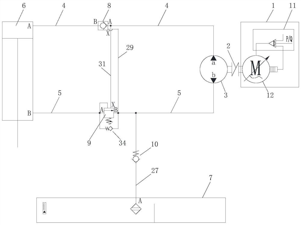
[0049] Such as figure 1 As shown, an electro-hydraulic servo pump drive device includes a servo drive mechanism 1, an oil cylinder 6 and an oil tank 7; the servo drive mechanism 1 includes a servo driver 11 and a servo motor 12, and the servo motor 12 is connected to the oil pump 3 through a coupling 2, so The inlet and outlet a of the oil pump 3 is connected to the inlet and outlet A of the oil cylinder 6 through the first pipeline 4, and the inlet and outlet b of the oil pump 3 is connected to the inlet and outlet B of the oil cylinder 6 through the second pipeline 5, wherein the inlet and outlet A communicate with the rodless chamber , the inlet and outlet B communicate with the rod cavity. The first outlet A of the oil tank 7 communicates with the second pipeline 5 through the oil outlet pipeline 27, and the oil outlet pipeline 27 is provided with a first valve 10 for controlling the on-off of the oil outlet pipeline 27. As preferably, the first valve 10 A one-way valve i...
Embodiment 2
[0058] Such as Figure 4 As shown, on the basis of the first embodiment above, a pressure maintaining oil circuit is provided. The pressure maintaining oil circuit includes a pressure maintaining pipeline 26, an air pump 14 and a third valve 13. One end of the pressure maintaining pipeline 26 is connected to the oil tank 7. The second outlet B is connected, and the other end is connected to the first pipeline 4 between the oil cylinder 6 and the second hydraulic lock 8. The pneumatic pump 14 and the third valve 13 are sequentially arranged on the pressure maintaining pipeline 26, and the pneumatic pump 14 On the side close to the oil tank 7 , the third valve 13 is close to the side of the first pipeline 4 .
[0059] Figure 4 The middle arrow indicates the flow direction of the oil circuit for replenishing hydraulic oil. The function of the pressure-holding oil circuit is to replenish the hydraulic oil. During the pressure process, when the pressure in the first pipeline 4 i...
Embodiment 3
[0061] Such as Figure 5 As shown, safety oil passages such as the first safety valve overflow oil passage, the second safety valve relief oil passage and the pre-pressure relief oil passage are provided on the basis of the first embodiment above, and the above safety oil passages can be set in the system One, two or three, set according to the needs of the system.
[0062] The function of the first safety valve overflow oil circuit: when the hydraulic oil in the first pipeline 4 exceeds the threshold set by the first overflow valve 15, the excess hydraulic oil can flow back to the oil tank 7 through the first overflow valve 15 . The first relief valve overflow oil circuit includes a first overflow valve 15 and a first overflow pipeline 36, one end of the first overflow pipeline 36 communicates with the oil return pipeline 18, and the other end is connected to the oil cylinder 6 and the second On the first pipeline 4 between the hydraulic locks 8, and communicate with the fi...
PUM
 Abstract
Description
Claims
Application Information
 - R&D Engineer
- R&D Manager
- IP Professional
- Industry Leading Data Capabilities
- Powerful AI technology
- Patent DNA Extraction
Browse by: Latest US Patents, China's latest patents, Technical Efficacy Thesaurus, Application Domain, Technology Topic, Popular Technical Reports.
© 2024 PatSnap. All rights reserved.Legal|Privacy policy|Modern Slavery Act Transparency Statement|Sitemap|About US| Contact US: help@patsnap.com