Dual-system absolute value encoder device and use method thereof

An absolute encoder and dual-system technology, applied in the encoder field, can solve the problems of inability to judge in time, wrong solution, low cost, etc., and achieve the effect of being beneficial to mass production and installation, improving position accuracy and low cost

Pending Publication Date: 2022-01-11
SHANGHAI ANPU MINGZHI AUTOMATION EQUIP
View PDF2 Cites 0 Cited by
  • Summary
  • Abstract
  • Description
  • Claims
  • Application Information

AI Technical Summary

Problems solved by technology

[0002] At present, there are three main solutions for photoelectric absolute value encoders: 1) Binary photocell: directly read the absolute position of a single turn when power is turned on. Disadvantages: high cost, fear of axial movement and oil vapor; 2) Vernier photocell : Low cost, disadvantages: afraid of axial movement and oil vapor, read the absolute position of the single circle through the cursor calculation when power on, if there is a slight change in the position, the cursor calculation is prone to calculation errors; 3) M-sequence photocells : Directly read the single-turn absolute position when power on. Disadvantages: high cost, not as sensitive to binary and vernier schemes for axial movement of oil vapor, but axial movement must be kept within 0.5mm
However, if there is a deviation in the combination of high and low bits of this type of encoder, the positioning accuracy of the encoder will deviate greatly, and this type of encoder solution requires the use of two magnetic induction chips, which is costly
In addition, when the encoder is abnormal, it cannot be judged in time

Method used


Image

  • Dual-system absolute value encoder device and use method thereof
  • Dual-system absolute value encoder device and use method thereof
  • Dual-system absolute value encoder device and use method thereof

Examples


Embodiment

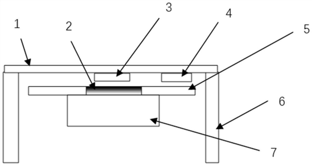
[0037] Such as figure 1 As shown, a dual-system absolute encoder device includes a PCB board 1, a magnet 2, a magnetic induction chip 3, a reflective induction chip 4, an incremental reflective code disc 5, an encoder bracket 6 and a code disc support 7; The PCB board 1 is placed on the encoder bracket 6 with the component side facing down; the magnet 2 is embedded in the center of the incremental reflective code disc 5; the magnetic induction chip 3 is located on the PCB board 1 and connected to the magnet 2 Coaxial installation; the incremental reflective code wheel 5 is placed on the code wheel holder 7; the reflective sensor chip 4 is located on the PCB board 1, wherein the reflective sensor chip 4 and the outer ring of the incremental reflective code wheel 5 relatively.

[0038] The dual-system absolute encoder device of the present invention includes a magnetic single-turn absolute encoder and an incremental reflective encoder, and the two encoders are mutually switched...


PUM


Abstract

The invention relates to a dual-system absolute value encoder device and a use method thereof. The dual-system absolute value encoder device comprises a PCB, a magnet, a magnetic induction chip, a reflective induction chip, an incremental reflective code disc, an encoder support and a code disc support. The PCB is arranged on the encoder support; the magnet is embedded in the dead center of the concentric circle where the incremental reflection type code disc is located. The magnetic induction chip is positioned on the PCB and is in induction arrangement with the magnet to form a magnetic single-loop absolute value encoder; the incremental reflection type code disc is arranged on the code disc support; the reflective sensing chip is located on the PCB, and the reflective sensing chip corresponds to a code channel of the incremental reflective coded disc to form an incremental reflective encoder; the magnet and the incremental reflection type code disc form a combined code disc, and the combined code disc, the magnetic induction chip and the reflection type induction chip achieve dual-system combination of the magnetic single-ring absolute value encoder and the incremental reflection type encoder. Compared with the prior art, the device has the advantages of small size, reliability, safety, high precision and the like.

Description

Technical field [0001] The present invention relates to the field of encoders, and in particular, to a dual-system absolute value encoder device and a method of using the same. Background technique [0002] Currently, there are three main solutions for photoelectric absolute encoders: 1) Binary photocell: directly reads the single-turn absolute position when powered on. Disadvantages: higher cost, fear of axial movement and oil vapor; 2) Vernier photocell : Lower cost. Disadvantages: Afraid of axial movement and oil vapor. When powered on, the single-turn absolute position is read through cursor calculation. If there is a slight change in the position, cursor calculation is prone to calculation errors; 3) M-series photovoltaic cells : Read single-turn absolute position directly when powering on. Disadvantages: high cost, not as sensitive to axial movement of oil vapor as binary and cursor solutions, but axial movement must be kept within 0.5mm. [0003] After searching, Chi...

Claims


Application Information

Patent Timeline
Patent Type & Authority Applications(China)
IPC IPC(8): G01D5/56
CPCG01D5/56
Inventor 胡君朱方田张荣
Owner SHANGHAI ANPU MINGZHI AUTOMATION EQUIP
Why Eureka
Try Eureka