Capacitor element withstand voltage test and performance measurement device and method

A technology of withstand voltage test and measuring equipment, which is applied in the direction of capacitance measurement, measuring electricity, and measuring devices. It can solve problems such as low efficiency, safety, and hidden dangers, and achieve high measurement accuracy, protect personnel and equipment, and improve measurement accuracy. Effect

Pending Publication Date: 2022-01-11
WUHAN NARI LIABILITY OF STATE GRID ELECTRIC POWER RES INST +3
0 Cites 0 Cited by

AI-Extracted Technical Summary

Problems solved by technology

The existing voltage withstand test of capacitor components is to pressurize the components with a DC power supply first, then discharge the components after completion, and then go to manual measurement. Since the voltage level of the test is re...

Method used

In technique scheme, described LCR digital electric bridge comprises current measuring equipment A1, the first voltage measuring equipment V1, the second voltage measuring equipment V2, resistance Rr and operational amplifier D1, wherein, one end of current measuring equipment A1 is grounded , the other end of the current measurement device A1 is connected to one end of the first voltage measurement device V1, the other end of the first voltage measurement device V1 is grounded, and one end of the first voltage measurement device V1 is used to connect the measured capacitor element (OUT in Figure 2 ), one end of the resistor Rr is used to connect the ground terminal of the capacitor component under test, the inverting input terminal of the operational amplifier D1 is connected to the ground terminal of the capacitor component under test, and the non-inverting input terminal of the operational amplifier D1 is grounded , the output end of the operational amplifier D1 is connected to the other end of the resistor Rr, one end of the second voltage measuring device V2 is connected ...

Abstract

The invention discloses a capacitor element withstand voltage test and performance measurement device and method. A direct-current power supply of the device is used for transmitting withstand voltage test direct-current voltage to a tested capacitor element; a contactor KM1 is used for controlling whether the tested capacitor element is connected with the withstand voltage test direct-current voltage or not; a contactor KM4 is used for controlling whether the grounding end of the tested capacitor element is grounded or not; and an LCR digital bridge is used for measuring the impedance, capacitance and inductance of the tested capacitor element. According to the invention, a high-voltage test unit and a low-voltage measurement unit are safely and smoothly switched by adopting an electrical method, the capacitance value and the dielectric loss are automatically read, the test time is saved, and the working efficiency is improved.

Application Domain

Capacitance measurementsReference comparison +1

Technology Topic

ContactorTested time +9

Image

  • Capacitor element withstand voltage test and performance measurement device and method
  • Capacitor element withstand voltage test and performance measurement device and method
  • Capacitor element withstand voltage test and performance measurement device and method

Examples

  • Experimental program(1)

Example Embodiment

[0022] Below in conjunction with accompanying drawing and specific embodiment the present invention is described in further detail:
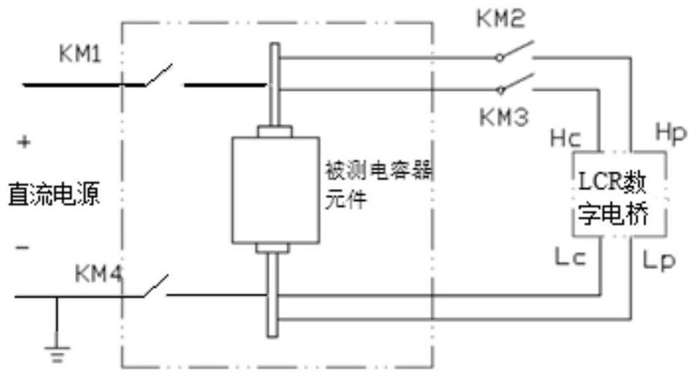
[0023] like Figure 1~3 The shown capacitor element withstand voltage test and performance measurement equipment, which includes DC power supply, contactor KM1, contactor KM4, LCR digital bridge, contactor KM2 and contactor KM3, contactor KM1, contactor KM2 and contactor KM3 It is a high-voltage vacuum contactor (rated voltage 10KV), and the contactor KM4 is a low-voltage contactor (220V);
[0024] The DC power supply is used to deliver the withstand voltage test DC voltage to the capacitor element under test;
[0025] The contactor KM1 is used to control whether the capacitor element under test is connected to the DC voltage of the withstand voltage test, that is, the positive pole of the DC power supply is connected through the contactor KM1 to control the input terminal of the DC voltage test of the capacitor element under test;
[0026] The contactor KM4 is used to control whether the ground terminal of the capacitor element under test is grounded, and to isolate the interference of the ground network to the measurement unit, that is, the negative pole of the DC power supply is connected to the ground terminal of the capacitor element under test through the contactor KM4;
[0027] The LCR digital bridge is used to measure the impedance, capacitance and inductance of the measured capacitor element, and the data communication end of the LCR digital bridge is connected to the communication end of the computer;
[0028] The contactor KM2 is used to connect the voltage high-voltage terminal H of the LCR digital bridge P It is connected with the withstand voltage test DC voltage input terminal of the capacitor element under test, and can realize the isolation of the voltage high voltage terminal H of the LCR digital bridge P connection to a DC power supply;
[0029] The contactor KM3 is used to transfer the current high end H of the LCR digital bridge C It is connected to the DC voltage input terminal of the withstand voltage test of the capacitor element under test, and can realize the isolation of the current high terminal H of the LCR digital bridge C connection to a DC power supply;
[0030] The voltage low-voltage terminal L of the LCR digital bridge P Connected to the ground terminal of the measured capacitor element, the current low terminal L of the LCR digital bridge C Connect to ground of the capacitor element under test.
[0031] The DC power supply is a high-voltage DC power supply, adopts a digital adjustable power supply, and has complete functions such as output DC voltage, holding time, discharge, and fault protection. The adjustable range of the DC voltage of the DC power supply is 0-5000V. The high-voltage input cable of the capacitor element under test is a 10KV high-voltage resistant cable;
[0032] In the above technical solution, the LCR digital bridge includes a current measurement device A1, a first voltage measurement device V1, a second voltage measurement device V2, a resistor Rr and an operational amplifier D1, wherein one end of the current measurement device A1 is grounded, and the current measurement The other end of the device A1 is connected to one end of the first voltage measuring device V1, the other end of the first voltage measuring device V1 is grounded, and one end of the first voltage measuring device V1 is used to connect the measured capacitor element ( figure 2 OUT) in the withstand voltage test DC voltage input terminal, one end of the resistor Rr is used to connect the ground terminal of the capacitor component under test, the inverting input terminal of the operational amplifier D1 is connected to the ground terminal of the capacitor component under test, and the non-inverting input terminal of the operational amplifier D1 is connected to the ground terminal of the capacitor component under test. The input end is grounded, the output end of the operational amplifier D1 is connected to the other end of the resistor Rr, one end of the second voltage measuring device V2 is connected to the output end of the operational amplifier D1, the other end of the second voltage measuring device V2 is grounded, and the other end of the current measuring device A1 One end is the current high end H of the LCR digital bridge C , one end of the first voltage measurement device V1 is the voltage high voltage end H of the LCR digital bridge P , the inverting input terminal of the operational amplifier D1 is the current low terminal L of the LCR digital bridge C , one end of the resistor Rr is the voltage high voltage end H of the LCR digital bridge P. to make H C 、H P , L P , L C Try to be as close to the DUT end as possible to reduce the measurement error, and the four connecting wires are as short as possible; the LCR digital bridge adopts the four-terminal measurement method, and the measurement accuracy is high.
[0033] In the above technical solution, it also includes a control module, the control module includes a normally open button switch SB1, a normally closed button switch SB2, a normally open button switch SB3, a normally open button switch SB4, a first relay and a second relay, the One end of the coil M1 of the first relay is connected to one end of the normally open button switch SB1, the other end of the normally open button switch SB1 is connected to one end of the normally closed button switch SB2, and the other end of the coil M1 of the first relay is connected to the normally closed of the second relay One end of the electric shock Z4, the two ends of the normally open contact K3 of the first relay are respectively connected to the two ends of the normally open button switch SB1, and the other end of the normally closed button switch SB2 is connected to the other end of the normally closed electric shock Z4 of the second relay. Both ends of the DC control power supply (DC24V, low voltage ensures safe operation);
[0034] The two ends of the normally closed contact K2 of the first relay are connected to the two ends of the DC control power supply, and the two ends of the normally open contact K1 of the first relay are connected to the two ends of the DC control power supply;
[0035] One end of the coil M2 of the second relay is connected to one end of the normally open button switch SB3, the other end of the normally open button switch SB3 is connected to one end of the normally closed button switch SB4, and the other end of the coil M2 of the second relay is connected to the first relay. One end of the normally closed contact K4, the two ends of the normally open contact Z3 of the second relay are respectively connected to the two ends of the normally open button switch SB3, the other end of the normally closed button switch SB4 is connected to the other end of the normally closed contact K4 of the first relay Connect to both ends of the DC control power supply;
[0036] The two ends of the normally open contact Z2 of the second relay are connected to the two ends of the DC control power supply, and the two ends of the normally closed contact Z1 of the second relay are connected to the two ends of the DC control power supply;
[0037]One end of the normally open contact K5 of the first relay is connected to one end of the contactor KM1 and one end of the contactor KM4, the other end of the normally open contact K5 of the first relay is connected to one end of the AC control power supply, and the other end of the contactor KM1 Connect the other end of the AC control power supply (AC220V) with the other end of the contactor KM4;
[0038] One end of the normally open contact Z5 of the second relay is connected to one end of the contactor KM2 and one end of the contactor KM3, the other end of the normally open contact Z5 of the second relay is connected to one end of the AC control power supply, the other end of the contactor KM2 and The other end of the contactor KM3 is connected to the other end of the AC control power supply. The normally open button switch SB1 and the normally closed button switch SB2 respectively control the on-off of the first relay and the self-locking of the first relay, and the normally open button switch SB3 and the normally closed button switch SB4 respectively control the on-off of the second relay and the second relay. Self-locking, the first relay and the second relay are interlocked to isolate the test part and the measurement part.
[0039] In the above technical solution, the control module also includes indicator lights S1 to S4, an indicator light S1 is provided between the normally open contact K1 of the first relay and the DC control power supply, and the normally closed contact K2 of the first relay is connected to the DC control power supply. There is an indicator light S2 between the DC control power supply, an indicator light S3 between the normally open contact Z2 of the second relay and the DC control power supply, and an indicator light between the normally closed contact Z1 of the second relay and the DC control power supply Light S4.
[0040] In the above technical solution, when the withstand voltage test is performed on the capacitor element under test, the indicator light S2 is on, press the normally open button switch SB1, the indicator light S1 is on, the indicator light S2 is off, the first relay operates, and at this time the contactor KM1 and contactor KM4 are closed; the DC power supply energizes the capacitor element under test to conduct a withstand voltage test. After the withstand voltage test is completed, the capacitor element under test is discharged, and when the output voltage of the capacitor element under test becomes 0, it is discharged. When finished, press the normally closed button switch SB2, the indicator light S2 is on, the indicator light S1 is off, the first relay is disconnected, the contactor KM1 and the contactor KM4 are disconnected, and the withstand voltage test is completed.
[0041] In the above technical solution, when performing performance measurement on the capacitor element under test, press the normally open button switch SB3, the indicator light S3 is on, the indicator light S4 is off, the second relay operates, the contactor KM2 and the contactor KM3 are closed; the LCR The digital bridge starts to measure the impedance, capacitance and inductance of the capacitor element under test; press the normally closed button switch SB4, the indicator light S4 is on, the indicator light S3 is off, the second relay is off, and the contactor KM2 and contactor KM3 are off. On, the measurement work is completed.
[0042] In the above technical solution, the first relay and the second relay are interlocked
[0043] In the above technical scheme, the impedance Z of the measured capacitor element x Calculated according to the following formula:
[0044] Z X =U X /I X =Rr*U x /U r
[0045] Among them, Rr is the standard resistance, U X is the voltage across the measured capacitor element, U r Is the voltage across the standard resistor Rr, I X For the current passing through the capacitor element under test, U is measured separately x and U r In-phase component and quadrature component, and then convert the in-phase component and quadrature component into digital quantities through analog-to-digital conversion, and then perform complex operations on the digital quantities of the in-phase component and quadrature component by the computer to obtain the measured The impedance Z of the capacitor element x resistance and reactance values.
[0046] A capacitor element withstand voltage test and performance measurement method utilizing the above-mentioned equipment, it comprises the steps:
[0047] Step 1: Control contactor KM1 and contactor KM4 to close, and control contactor KM2 and contactor KM3 to open at the same time, the capacitor element under test is connected to the DC power supply for withstand voltage test, and the capacitor element under test is discharged after the withstand voltage test is completed. After the voltage of the capacitor element under test becomes 0, enter step 2;
[0048] Step 2: Turn on the LCR bridge, set up, enter CS/D (capacitor C x and dielectric loss tangent D) mode, frequency 50HZ, voltage 2V, control contactor KM1 and contactor KM4 to open, control contactor KM2 and contactor KM3 to close at the same time, and measure the performance of the capacitor element under test through the LCR digital bridge , to get the impedance Z of the capacitor element under test x , capacitance C x , resistor R x , according to D=tgδ=R x /Z x , Automatically calculate the dielectric loss tangent D.
[0049] The invention adopts the method of electric control switching, smoothly connects the link of withstand voltage test and measurement, saves the link of manual disassembly and assembly, greatly improves the efficiency, and protects the safety of test personnel.
[0050] The content not described in detail in this specification belongs to the prior art known to those skilled in the art.

PUM

no PUM

Description & Claims & Application Information

We can also present the details of the Description, Claims and Application information to help users get a comprehensive understanding of the technical details of the patent, such as background art, summary of invention, brief description of drawings, description of embodiments, and other original content. On the other hand, users can also determine the specific scope of protection of the technology through the list of claims; as well as understand the changes in the life cycle of the technology with the presentation of the patent timeline. Login to view more.

Similar technology patents

Device for removing low-melting-point alloy from inner cavity of blade

ActiveCN106761953Ashort removal timeImprove work efficiency
Owner:CHINA HANGFA SOUTH IND CO LTD

Caking fertilizer crushing device for agriculture big data

Owner:安徽众力农业装备科技有限公司

Classification and recommendation of technical efficacy words

  • Improve work efficiency

Cooperation service platform facing different source data

InactiveCN101174957AImprove management level and qualityImprove work efficiency
Owner:NANJING UNIV OF FINANCE & ECONOMICS

Screw drilling tool, vertical drilling tool testing method and well inclination simulation testing equipment

InactiveCN111594144AReduced height requirementsImprove work efficiency
Owner:DEZHOU UNITED GASOLINEEUM MACHINERY

Method for intelligent automatic identification of transmission circuit parts

Owner:INFORMATION COMM COMPANY STATE GRID SHANDONG ELECTRIC POWER +2

Keyboard spill-proofing mechanism

ActiveUS7030330B2minimize manufacturing costimprove work efficiency
Owner:LITE ON SINGAPORE PTE LTD
Why Eureka
Try Eureka