Computer room on-site wiring equipment

A technology for computer room and wiring equipment, which is applied in the direction of cable laying equipment, etc. It can solve the problems of easy aging and falling off of labels, maintenance troubles, and wear and tear of calibration characters, so as to improve rapid identification, avoid difficulties in installation, maintenance and traceability, and not easy to be damaged Effect

Active Publication Date: 2022-01-11
ANSHAN NORMAL UNIV
View PDF6 Cites 0 Cited by
  • Summary
  • Abstract
  • Description
  • Claims
  • Application Information

AI Technical Summary

Problems solved by technology

In the wiring construction of the computer room, the traditional wiring is manually attached with simple labels to number the network cables, so as to mark the network cables. Due to the large number of network cables, the number of calibrations is large, and manual calibration symbols generally use self-made Inputting and writing may easily lead to duplication of labels or inconsistencies between the beginning and the end, and the error rate is high, which brings troubles to subsequent maintenance. At the same time, as the computer room is put into use and the maintenance work is carried out, the labels are often prone to aging and falling off or the calibration characters Wear and tear, because the computer room, especially the server in the data center, is generally laid out in a concentrated manner, and multiple groups of network cables are concentrated into bundles, which makes it difficult to trace the source of the network cables

Method used


Image

  • Computer room on-site wiring equipment
  • Computer room on-site wiring equipment
  • Computer room on-site wiring equipment

Examples


Embodiment Construction

[0025] The present invention will be further described in detail below in conjunction with the accompanying drawings and examples. The following examples are explanations of the present invention and the present invention is not limited to the following examples.

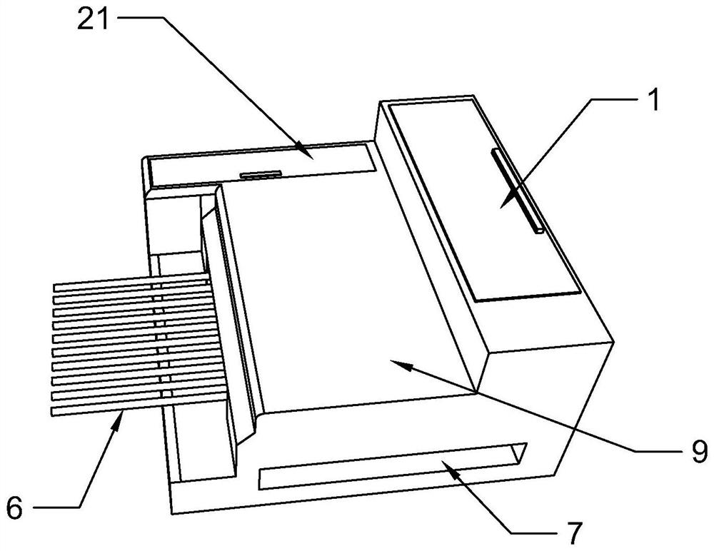
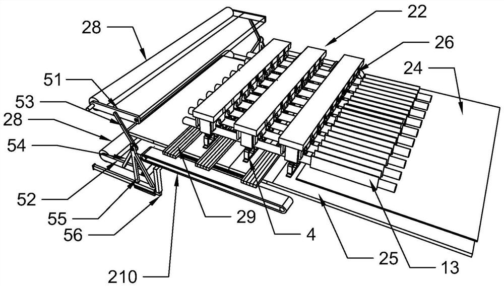
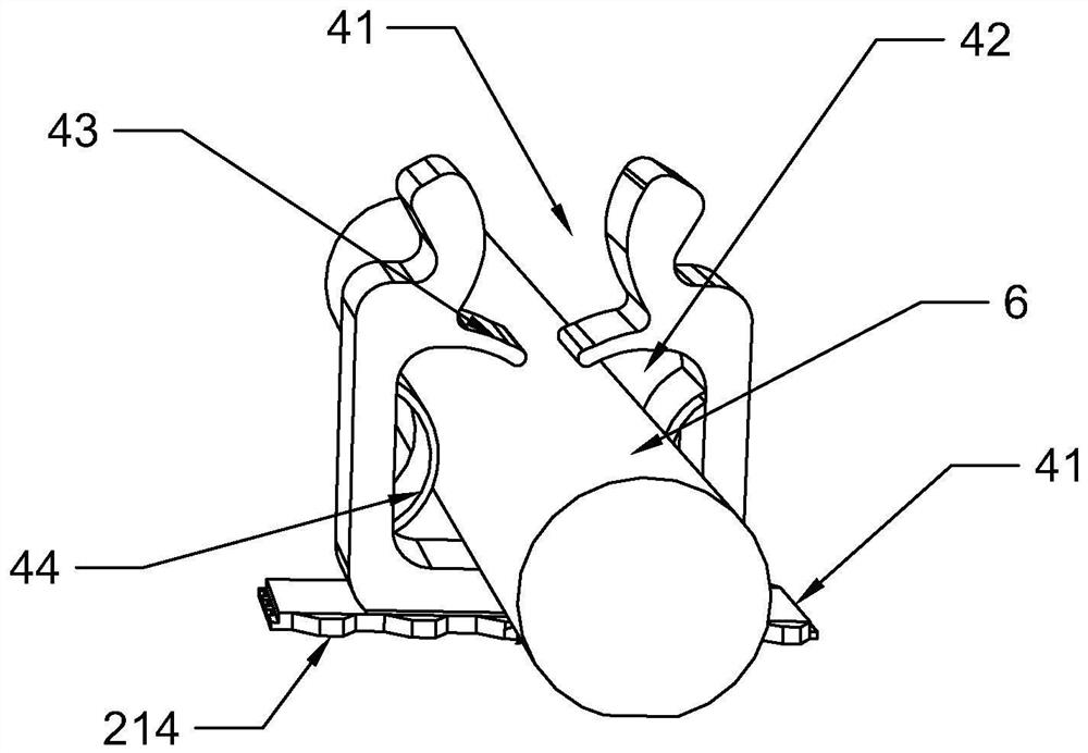
[0026] see Figure 1-Figure 8 In this embodiment, a field wiring device for a computer room includes a wire winding unit 1 and a marking unit, and several groups of winding wheels for winding wires 6 are rotated on a support frame, and the wires 6 are driven by a wire transmission roller set 11 The longitudinal routing of the wire 6 is provided with a wire 6 cutting knife adjacent to the position of the winding wheel (the cutting knife moving up and down is used to contact and cut the wire 6 of the upper plate 24), and the marking unit includes a marking buckle winding module 21 and Press the material cutting module 22, and the described marking buckle winding module 21 has a plurality of buckle parts 4 arranged and...


PUM


Abstract

The invention discloses computer room on-site wiring equipment. The equipment comprises a wire winding unit and a marking unit, a plurality of winding wheels for winding wires are rotationally arranged on a supporting frame, the wires are longitudinally arranged through a wire conveying driving roller set, a wire cutting knife is arranged at the position close to the winding wheels, the marking unit comprises a marking buckle winding module and a pressing and cutting module, and the marking buckle winding module is formed by sequentially arranging and winding a plurality of buckle pieces. The structural design is reasonable, the cable conveying driving roller set driven by the motor is adopted, output of the preset length can be achieved, the cable of the corresponding length does not need to be manually measured, meanwhile, automatic numbering of the network cables is achieved through the marking unit in a buckling mode, installation, repair, maintenance and traceability difficulties caused by complexity of manual numbering and repeated numbering are avoided, meanwhile, the bayonet piece structure is convenient to clamp, meanwhile, marks are not prone to damage, a plurality of bayonet sets can be arranged at the end according to requirements, permutation and combination forms are diversified and are not prone to repetition, and meanwhile, different colors are marked on the fasteners of each group of numbers, so that the quick identification is improved.

Description

technical field [0001] The invention relates to the field of computer database equipment, in particular to field wiring equipment in a computer room. Background technique [0002] The construction of the computer room is a systematic project. It should start from the needs of the work, be people-oriented, meet the functional needs, take into account the aesthetics and practicality, provide a safe operating space for the equipment, and create a good working environment for the staff engaged in computer operations. In the wiring construction of the computer room, the traditional wiring is manually attached with simple labels to number the network cables, so as to mark the network cables. Due to the large number of network cables, the number of calibrations is large, and manual calibration symbols generally use self-made Inputting and writing may easily lead to duplication of labels or inconsistencies between the beginning and the end, and the error rate is high, which will cau...

Claims


Application Information

Patent Timeline
Patent Type & Authority Applications(China)
IPC IPC(8): H02G1/06
CPCH02G1/06Y02W30/82
Inventor 奚慧兴
Owner ANSHAN NORMAL UNIV
Why Eureka
Try Eureka