Interface identification circuit, interface identification method and intelligent terminal
A technology for interface identification and intelligent terminals, which is applied in the direction of circuit devices, battery circuit devices, safety/protection circuits, etc., can solve the problem of large space occupation and achieve the effect of saving space
- Summary
- Abstract
- Description
- Claims
- Application Information
AI Technical Summary
Problems solved by technology
Method used
Image
Examples
no. 1 example
[0081] An embodiment of the present application discloses an interface identification circuit. The smart terminal includes an interface with identification pins. The smart terminal may be the smart terminal in the above embodiments, or may be a speaker, a game console, or a smart wearable device. Optionally, the smart wearable device may include a smart bracelet, a smart watch, a smart armband, and the like. Optionally, the interface of the above intelligent terminal may be a TYPE-C interface.
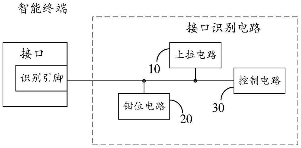
[0082] image 3 Shows a schematic diagram of the circuit structure of the interface identification circuit of this embodiment, refer to image 3 As shown, the interface identification circuit includes a pull-up circuit 10 electrically connected to the identification pin of the interface, a control circuit 20 and a clamping circuit 30; the control circuit 30 is used to detect the target of the identification pin when an external device is connected to the interface Voltage, according ...
no. 2 example
[0089] refer to Figure 4 , based on the first embodiment, the present application proposes a second embodiment. In this embodiment, the identification pin includes a CC1 pin and a CC2 pin, and the pull-up circuit 10 includes a first resistor R1, a second resistor R2, a Three resistors R3 and power supply terminals; the first end of the first resistor R1 is connected to the CC1 pin, the first end of the second resistor R2 is connected to the CC2 pin; the second end of the first resistor R1, the second end of the second resistor R2 The two terminals, the second terminal of the third resistor R3 are connected to the control circuit 30 respectively, and the first terminal of the third resistor R3 is connected to the power supply terminal.
[0090] It should be understood that, as can be seen from the content of the first embodiment, the CC pin of the external device is provided with a corresponding pull-down resistor according to the TYPE-C protocol. The CC pins of external devi...
no. 3 example
[0098] refer to Figure 5 , based on the second embodiment, the present application proposes a third embodiment, the interface identification circuit also includes:
[0099] A filter circuit 40, the filter circuit 40 is connected in series in the path between the identification pin and the control circuit 30, the filter circuit 40 is used to filter out the signal sent by the charging device through the interface when the charging device is connected to the interface.
[0100] In this embodiment, when the charging device, especially the PD device is connected, it can be seen from the third embodiment above that the clamping circuit will clamp the voltage of the CC pin of the interface within the preset voltage range and the PD device is turned on start working. When the PD device starts to work, it will continuously output signals through the CC pin on the smart terminal interface. Optionally, the PD device will send a message signal when it is working, and the voltage of the ...
PUM
 Abstract
Description
Claims
Application Information
 - R&D
- Intellectual Property
- Life Sciences
- Materials
- Tech Scout
- Unparalleled Data Quality
- Higher Quality Content
- 60% Fewer Hallucinations
Browse by: Latest US Patents, China's latest patents, Technical Efficacy Thesaurus, Application Domain, Technology Topic, Popular Technical Reports.
© 2025 PatSnap. All rights reserved.Legal|Privacy policy|Modern Slavery Act Transparency Statement|Sitemap|About US| Contact US: help@patsnap.com


