Generator rotor claw pole angle control device

A generator rotor and angle control technology, which is applied in electromechanical devices, manufacturing motor generators, manufacturing stator/rotor bodies, etc., can solve problems such as high requirements for the shape of claw poles, difficult automatic flow operation, and complex tooling structure, etc., to achieve Convenient and efficient movement, convenient tooling replacement and adjustment, and improved dimensional accuracy

Pending Publication Date: 2022-01-11
浙江大东吴汽车电机股份有限公司
View PDF7 Cites 0 Cited by
  • Summary
  • Abstract
  • Description
  • Claims
  • Application Information

AI Technical Summary

Problems solved by technology

[0005] This technical solution uses the vertical V-shaped fork to control the uniformity of the angle of the claw pole through the limit during the process of the generator rotor entering the shaft. Due to the vertical V-shaped fork limit method, the structure of the tooling is complicated and the size of the tooling is large. , it is difficult to realize automatic flow operation, and the tooling using the vertical V-shaped fork limit method has higher requirements on the shape of the claw pole. If the shape of the claw pole is slightly deviated, it will easily cause the dislocation between the shape of the tooling and the shape of the blank. At the same time, when When changing the claw pole model, it is necessary to manually adjust the position of the V-shaped fork, which takes a long time to change the model

Method used


Image

  • Generator rotor claw pole angle control device
  • Generator rotor claw pole angle control device
  • Generator rotor claw pole angle control device

Examples


Embodiment

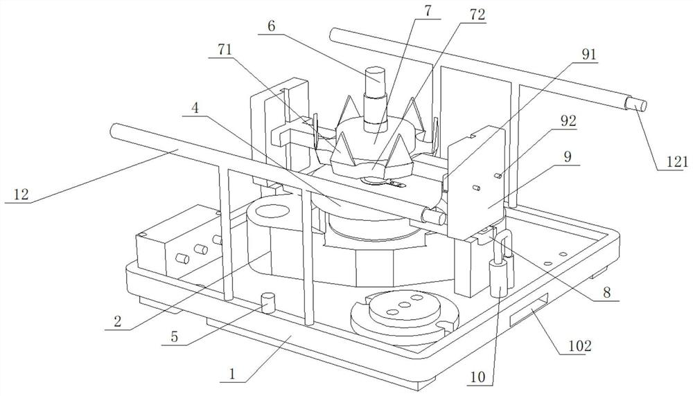
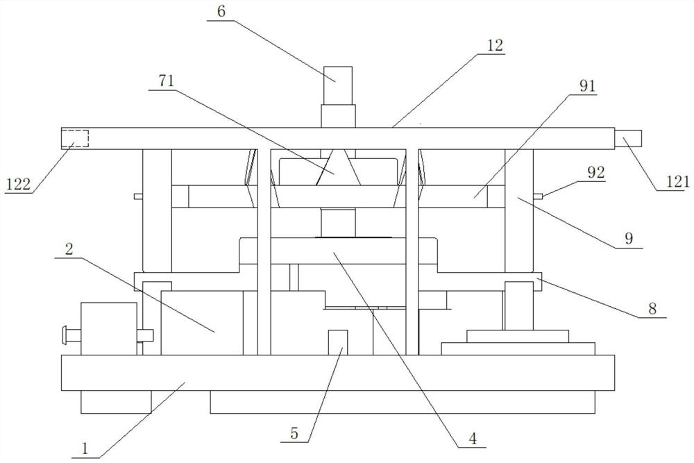
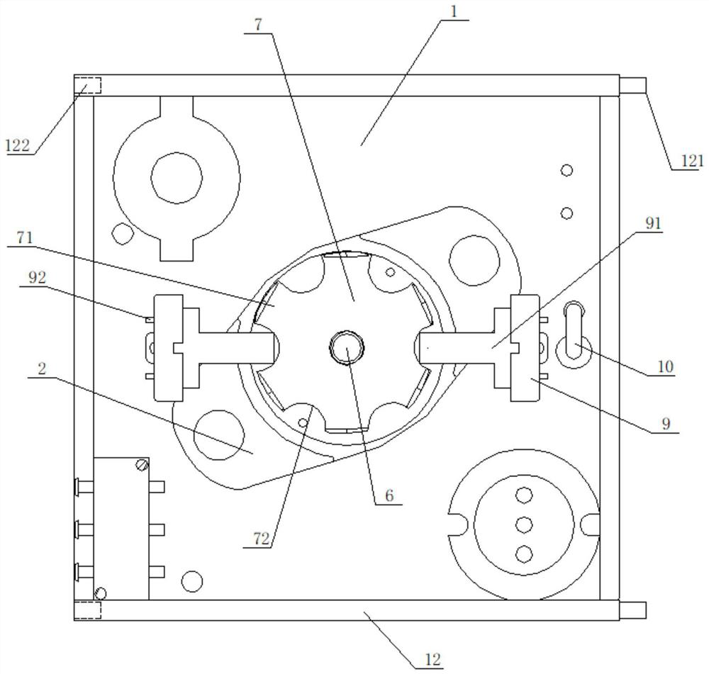
[0038] as attached figure 1 to attach Figure 4 As shown, the present invention provides a generator rotor claw pole angle control device, which includes an assembly line tray 1 and a base 2. It is characterized in that a socket 101 is installed on the left side of the assembly line tray 1, and a socket 101 is installed on the right side of the assembly line tray 1. Socket 102, the upper part of the assembly line tray 1 is provided with a base 2.

[0039] as attached Image 6 to attach Figure 8 As shown, in the above embodiment, specifically, a fixed drive motor 5 is installed on the upper side of the assembly line tray 1, and a drive shaft 51 is provided at the bottom of the fixed drive motor 5, and helical gears are installed at the bottom of the drive shaft 51. One 52 , the side of the first helical gear 52 is meshed with the second helical gear 53 , and the second helical gear 53 is fixedly mounted on the first driven shaft 54 ​​.

[0040] as attached figure 1 to att...


PUM


Abstract

The invention provides a generator rotor claw pole angle control device, and belongs to the field of generator rotor structure equipment. The device comprises an assembly line tray and a base, and is characterized in that the left side of the assembly line tray is provided with a socket, the right side of the assembly line tray is provided with a jack, and the upper part of the assembly line tray is provided with the base. According to the invention, the claw pole grooves are clamped by a horizontal push plate, so that the relative positions of the claw poles and a generator rotor shaft are uniform, and the effect of reducing noise is achieved; the assembly line tray is combined with the rotor structure, and the single claw pole is inserted into the rotor shaft, so that the effect of convenient and automatic production is achieved; the push-out and retraction actions of the horizontal push plate are adopted, so that the requirement on the non-key overall dimension of the claw pole is reduced, the tool is prevented from being stuck, and the tool replacement and adjustment efficiency is improved; the multiple devices are connected by a fixed driving motor, a fixed base and the like, and meanwhile the effect of conveniently and efficiently moving the multiple devices is achieved through the handles on the two sides of the assembly line tray.

Description

technical field [0001] The invention relates to the field of generator rotor structural equipment, in particular to a generator rotor claw pole angle control device. Background technique [0002] Generator Rotor The rotating part of a generator. The generator rotor is mainly composed of a shaft, a coil assembly, a collector ring and two claw poles. The rotor is an important part of the alternator. After the generator is pre-excited, it will generate a magnetic field. During operation, it will generate current by cutting the magnetic induction line, so as to achieve the effect of power generation. The rotor is a key component inside the generator. [0003] The patent application number is CN201120306896.8 provides a generator rotor claw pole structure, including a claw pole body and a plurality of claw poles arranged on the claw pole body, the bottom surface of the claw pole body is the connecting surface of the fan blade. A chamfer is provided at the intersection of the b...

Claims


Application Information

Patent Timeline
Patent Type & Authority Applications(China)
IPC IPC(8): H02K15/02
CPCH02K15/022
Inventor 陈骏王滔涛姚素伟
Owner 浙江大东吴汽车电机股份有限公司
Why Eureka
Try Eureka