
Metal powder separation device and using method thereof

A metal powder and separation device technology, which is applied in the field of metal powder separation devices and metal powder separation devices, can solve the problems of not removing metal powder metal powder well, unfavorable work efficiency, and long time, so as to facilitate popularization , simple structure and low cost

Pending Publication Date: 2022-01-14
JIANGSU VILORY ADVANCED MATERIALS TECH CO LTD
View PDF6 Cites 0 Cited by
  • Summary
  • Abstract
  • Description
  • Claims
  • Application Information

AI Technical Summary

Problems solved by technology

[0004] Notification number CN212349084U discloses a vibrating separator for metal powder material balls, comprising a screen body, a rotating motor, a lead screw, a first lead screw platform, a second lead screw platform and a fixing seat, one end of the screen body is connected to the first lead screw The other end of the screen body is fixedly connected with the fixed ring, and the fixed ring is fixedly connected with the axial direction of the connecting ring. The circumferential direction of the screen body is provided with a feeding channel. The ends are fixedly connected with the first screw table and the second screw table respectively, the rotating motor is connected with the first screw table in rotation, the first screw table is connected with the first rotating seat in rotation, and the separation device is Metal powders of different particle sizes are separated through the sieve body and vibration. Due to the large number of metal powder particles, it takes a long time to sieve and separate through the sieve plate, which is not conducive to the improvement of work efficiency, and it is not well removed. Smaller particle size metal powder among metal powders

Method used


Image

  • Metal powder separation device and using method thereof
  • Metal powder separation device and using method thereof
  • Metal powder separation device and using method thereof

Examples


Embodiment 1

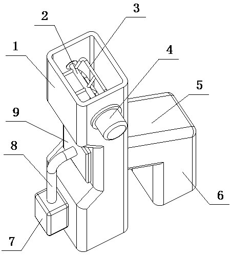
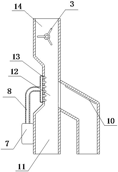
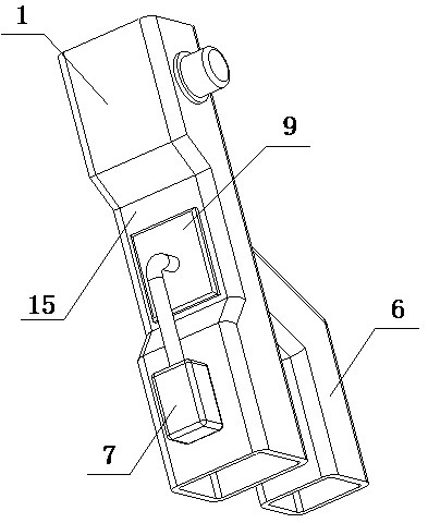
[0046] A metal powder separation device of the present invention is realized in the following way: a metal powder separation device of the present invention includes a feeding cylinder (1), a separation assembly placed on one side of the feeding cylinder (1) and a separation assembly placed on the feeding cylinder the discharge assembly on the other side of the body (1),

[0047] It is characterized in that the separation component separates the metal powder in the delivery cylinder (1), and the separated metal powder is discharged through the discharge component.

[0048] The feeding cylinder (1) is a long cylindrical structure with openings at both ends,

[0049]The feeding cylinder (1) is divided into three parts, the part near one end of the feeding cylinder (1) is the feeding chamber (14), and the middle part of the feeding cylinder (1) is the separation chamber (12) , the part near the other end of the feeding cylinder (1) is the discharge chamber (11), the feed chamber...

Embodiment 2

[0062] The difference between this embodiment and Embodiment 1 is that an extension plate (16) is disposed at the entrance of the separation chamber (12), one end of the extension plate (16) is connected to the inner wall of one side of the separation chamber (12), and the other end is inclined Extending downward for a certain distance, the angle between the extension plate (16) and the inner wall of one side of the separation chamber (12) is an acute angle; when in use, it can guide the metal powder so that the metal powder is close to the separation output pipe (5 ), so that the airflow blows the metal powder into the separation output pipe (5);

Embodiment 3

[0064] The difference between this embodiment and Embodiment 2 is that there are multiple groups of leakage holes (17) equidistant on the extension plate (16); when in use, the metal powder falling into the separation chamber (12) can be horizontally Layering in the direction facilitates the separation of metal powder by air flow;


PUM


Abstract

The invention relates to a metal powder separation device and a using method thereof, and discloses a separation device for pre-separating metal powder by utilizing airflow to facilitate subsequent fine separation and a using method of the separation device. The metal powder separation device comprises a material conveying barrel, a separation assembly arranged on one side of the material conveying barrel and a discharging assembly arranged on the other side of the material conveying barrel, and is characterized in that the separation assembly separates metal powder in the material conveying barrel; the separated metal powder is discharged through the discharging assembly; the material conveying barrel is of a long-strip-shaped barrel-shaped structure with the two ends open; the material conveying barrel is divided into three parts; the part, close to one end, of the material conveying barrel is a feeding cavity; the middle part of the material conveying barrel is a separation cavity; the part, close to the other end, of the conveying barrel is a discharging cavity; the feeding cavity is communicated with the separation cavity; the separation cavity is communicated with the discharging cavity; the feeding cavity is located above the separation cavity; and the separation cavity is located above the discharging cavity.

Description

technical field [0001] The invention relates to a metal powder separation device and a use method thereof, relating to a metal powder separation device and a use method thereof, which belong to the field of powder processing. In particular, it relates to a separation device for pre-separation of metal powder by air flow to facilitate subsequent fine separation and its use method. Background technique [0002] During the production of metal powder, due to the production process of its production equipment, the particle size of the produced metal powder will be different. Since the density of the metal powder in the same batch is similar, the weight of the metal powder with a large particle size is relatively heavy, and Metal powders with different particle sizes will have different effects on the forming and quality of parts, so it is necessary to separate the metal powder. There is usually no preliminary separation operation for the separation of large and small metal powde...

Claims


Application Information

Patent Timeline
Patent Type & Authority Applications(China)
IPC IPC(8): B07B4/02B07B11/06B07B11/00B02C19/00B02C23/08
CPCB07B4/02B07B11/06B07B11/00B02C19/00B02C23/08
Inventor 叶国晨蒋保林许荣玉张柯唐跃跃魏放杨德宗李兆宽
Owner JIANGSU VILORY ADVANCED MATERIALS TECH CO LTD
Learn More