Steel bar bending and straightening conversion device
A conversion device and steel bar bending and straightening technology, applied in the direction of manufacturing tools, metal processing, metal processing equipment, etc., can solve the problems of low processing efficiency, large floor space, increased cost expenditure, etc., to improve processing efficiency and small floor space , low cost effect
- Summary
- Abstract
- Description
- Claims
- Application Information
AI Technical Summary
Problems solved by technology
Method used
Image
Examples
Embodiment 1
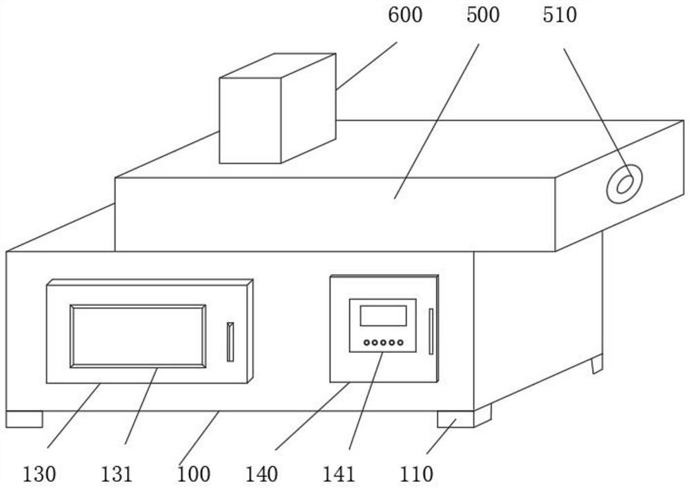
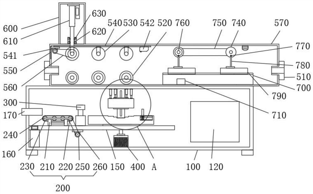
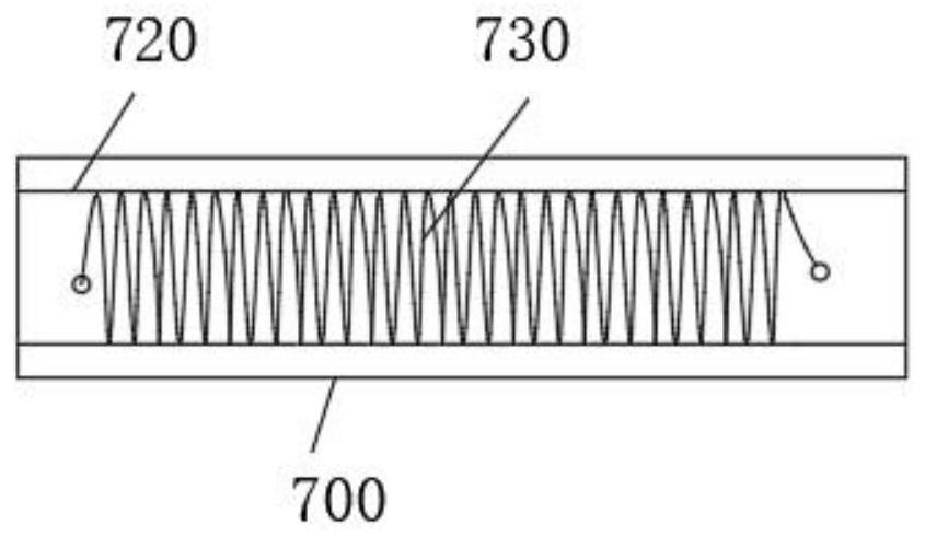
[0031]Please refer to the figure, the present invention provides a technical solution: steel bar bending straight conversion device, including bending box 100, feeding mechanism 200, clamping mechanism 300, second motor 400, straightening box 500, protective box 600 and heating seat 700, feeding The mechanism 200 is located on the left side of the inner cavity of the bending box 100, the clamping mechanism 300 is located on the left side of the inner cavity of the bending box 100, and is located on the right side of the feeding mechanism 200, and the second motor 400 is fixedly connected in the middle of the bottom of the inner cavity of the bending box 100 , the straightening box 500 is fixedly connected to the top of the bending box 100, the protective box 600 is fixedly connected to the top left side of the straightening box 500, the heating seat 700 is fixedly connected to the bottom right side of the inner cavity of the straightening box 500, and the bending box 100 The su...
Embodiment 2
[0033] Please refer to the figure, the present invention provides a technical solution: steel bar bending straight conversion device, including bending box 100, feeding mechanism 200, clamping mechanism 300, second motor 400, straightening box 500, protective box 600 and heating seat 700, feeding The mechanism 200 is located on the left side of the inner cavity of the bending box 100, the clamping mechanism 300 is located on the left side of the inner cavity of the bending box 100, and is located on the right side of the feeding mechanism 200, and the second motor 400 is fixedly connected in the middle of the bottom of the inner cavity of the bending box 100 , the straightening box 500 is fixedly connected to the top of the bending box 100, the protective box 600 is fixedly connected to the top left side of the straightening box 500, the heating seat 700 is fixedly connected to the bottom right side of the inner cavity of the straightening box 500, and the bending box 100 The s...
Embodiment 3
[0035]Please refer to the figure, the present invention provides a technical solution: steel bar bending straight conversion device, including bending box 100, feeding mechanism 200, clamping mechanism 300, second motor 400, straightening box 500, protective box 600 and heating seat 700, feeding The mechanism 200 is located on the left side of the inner cavity of the bending box 100, the clamping mechanism 300 is located on the left side of the inner cavity of the bending box 100, and is located on the right side of the feeding mechanism 200, and the second motor 400 is fixedly connected in the middle of the bottom of the inner cavity of the bending box 100 , the straightening box 500 is fixedly connected to the top of the bending box 100, the protective box 600 is fixedly connected to the top left side of the straightening box 500, the heating seat 700 is fixedly connected to the bottom right side of the inner cavity of the straightening box 500, and the bending box 100 The su...
PUM
 Abstract
Description
Claims
Application Information
 - R&D Engineer
- R&D Manager
- IP Professional
- Industry Leading Data Capabilities
- Powerful AI technology
- Patent DNA Extraction
Browse by: Latest US Patents, China's latest patents, Technical Efficacy Thesaurus, Application Domain, Technology Topic, Popular Technical Reports.
© 2024 PatSnap. All rights reserved.Legal|Privacy policy|Modern Slavery Act Transparency Statement|Sitemap|About US| Contact US: help@patsnap.com


