

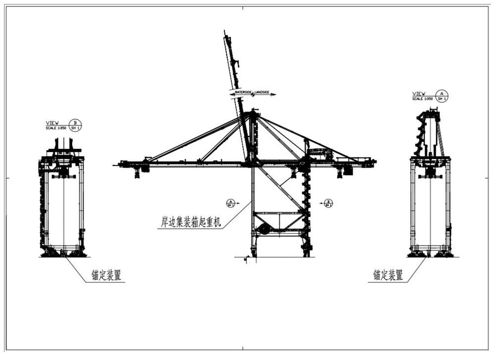
Port machinery windproof anchoring device capable of compensating seismic motion
An anchoring device and seismic motion technology, which is applied in the field of port loading and unloading equipment, can solve the problems of poor consideration of the dynamic response of the quay crane structure, the failure of the anchor pin to compensate for the seismic displacement, the buckling deformation of the door frame and the front girder, etc. Achieve the effect of improving international competitiveness, improving safety and personnel safety, and avoiding structural damage
- Summary
- Abstract
- Description
- Claims
- Application Information
AI Technical Summary
Problems solved by technology
Method used
Image

Examples
Embodiment Construction
[0037] It should be noted that, in the case of no conflict, the embodiments of the present invention and the features in the embodiments can be combined with each other. The present invention will be described in detail below with reference to the accompanying drawings and examples.
[0038] In order to make the purpose, technical solutions and advantages of the embodiments of the present invention clearer, the technical solutions in the embodiments of the present invention will be clearly and completely described below in conjunction with the drawings in the embodiments of the present invention. Obviously, the described embodiments It is only some embodiments of the present invention, but not all embodiments. The following description of at least one exemplary embodiment is merely illustrative in nature and in no way taken as limiting the invention, its application or uses. Based on the embodiments of the present invention, all other embodiments obtained by persons of ordina...
PUM
 Abstract
Description
Claims
Application Information