
Microbial fermentation tank

A microbial fermentation and tank technology, applied in the field of fermentation tanks, can solve problems such as autolysis, bacterial respiration obstruction, and metabolic abnormal bacteria, and achieve the effects of ensuring sensitivity, preventing foam accumulation, and ensuring normal metabolism

Pending Publication Date: 2022-01-14
蒋泽林
View PDF1 Cites 0 Cited by
  • Summary
  • Abstract
  • Description
  • Claims
  • Application Information

AI Technical Summary

Problems solved by technology

[0004] Although the comparative patent can automatically detect the foam or liquid level through the defoamer sensor, and automatically add and measure the defoamer, the fermenter only adds the defoamer from one port, which may cause insufficient defoamer addition. Uniform phenomenon; because the foam formed by fermentation is divided into two types: foam on the surface of the fermentation liquid and foam in the fermentation liquid, and the defoamer sensor of the fermenter is set on the top of the tank, which will cause defoamer induction When the sensor senses the foam, the foam has accumulated a certain amount, and the foam cannot be eliminated in time, resulting in a large amount of liquid escape, and the fermentation liquid escapes from the exhaust pipe or shaft seal, which increases the chance of bacterial contamination, etc. In severe cases, ventilation and stirring cannot be carried out. , bacterial respiration is hindered, resulting in abnormal metabolism or bacterial autolysis

Method used


Image

  • Microbial fermentation tank
  • Microbial fermentation tank
  • Microbial fermentation tank

Examples


Embodiment Construction

[0031] The following will clearly and completely describe the technical solutions in the embodiments of the present invention with reference to the accompanying drawings in the embodiments of the present invention. Obviously, the described embodiments are only some, not all, embodiments of the present invention. Based on the embodiments of the present invention, all other embodiments obtained by persons of ordinary skill in the art without making creative efforts belong to the protection scope of the present invention.

[0032] In describing the present invention, it is to be understood that the terms "center", "longitudinal", "transverse", "length", "width", "thickness", "upper", "lower", "front", " Back", "Left", "Right", "Straight", "Horizontal", "Top", "Bottom", "Inner", "Outer", "Clockwise", "Counterclockwise", etc. or The positional relationship is based on the orientation or positional relationship shown in the drawings, which is only for the convenience of describing t...


PUM


Abstract

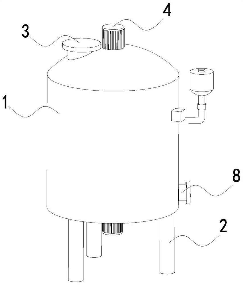
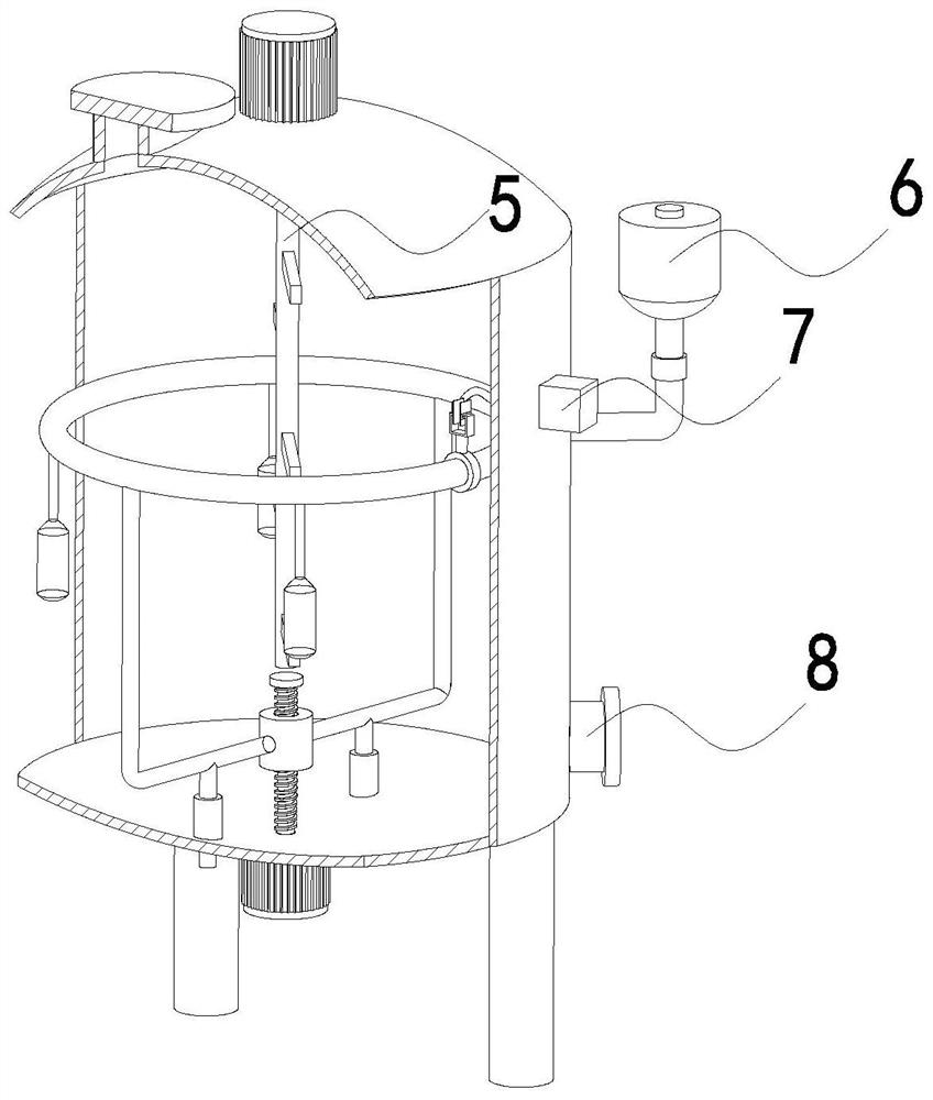
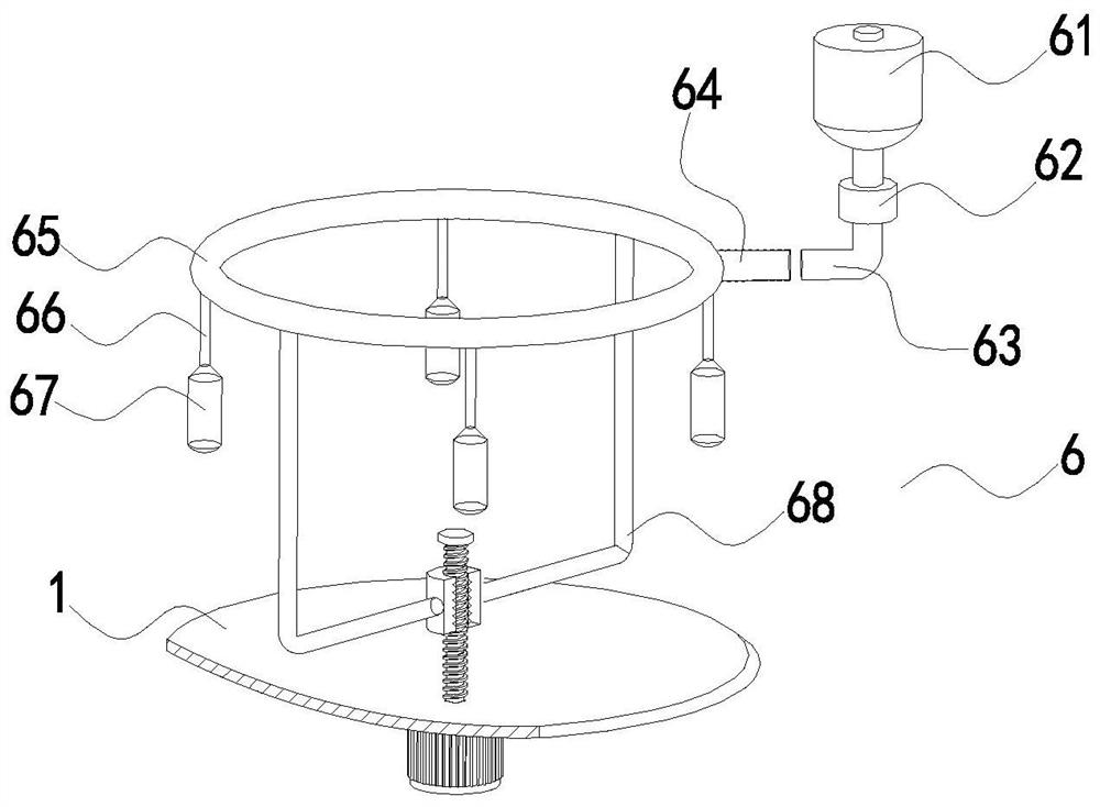
The invention relates to the technical field of fermentation tanks, in particular to a microbial fermentation tank which comprises a tank body, and evenly-distributed foot supporting columns are annularly and fixedly connected to the edge position of the lower surface of the tank body; a stirring motor is fixedly connected to the middle position of the upper surface of the tank body; a feeding port is formed in one side, close to the stirring motor, of the upper surface of the tank body; an output shaft of the stirring motor is fixedly connected with a stirring shaft, and the lower end of the stirring shaft penetrates through the upper surface of the tank body and extends into the tank body; an injection mechanism is arranged in a cavity of the tank body, and the injection mechanism penetrates through the side wall of the tank body and extends out of the tank body; an early warning mechanism is fixedly mounted at the upper end of one side of the outer surface of the tank body, and the early warning mechanism penetrates through the side wall of the tank body and extends into the tank body; a discharge port is formed in the lower end of one side of the outer surface of the tank body. According to the invention, foams generated by microbial fermentation in the fermentation tank can be uniformly eliminated, and normal metabolism of microorganisms is ensured.

Description

technical field [0001] The invention relates to the technical field of fermentation tanks, in particular to a microbial fermentation tank. Background technique [0002] Microbial fermentation tank refers to the device used for microbial fermentation in industry. Its main body is generally a columnar cylinder made of stainless steel plate. Reasonable, can withstand steam sterilization, have certain operating flexibility, minimize internal accessories (avoid dead ends), strong material and energy transfer performance, and can be adjusted to facilitate cleaning and reduce pollution, suitable for the production of various products and Reduce energy consumption. [0003] Chinese patent discloses a microbial fermenter, the patent application number is CN201521112657.3, a fermenter for continuous microbial culture, including a fermenter body, the top of the fermenter body is respectively equipped with a defoamer sensor, an air outlet, Adding port for acid adjustment, adding port ...

Claims


Application Information

Patent Timeline
IPC IPC(8): C12M1/02C12M1/21C12M1/36C12M1/00
CPCC12M23/48C12M27/02C12M33/00C12M41/02C12M41/48
Inventor 蒋泽林刘飞
Owner 蒋泽林
Learn More