
Composite rolling shock isolation device with UI limiters

A rolling vibration isolation and stopper technology, applied in protection devices, buildings, infrastructure engineering, etc., can solve problems such as human survival and ecological environment impact, production and national economic losses, fire and environmental pollution, etc. The effect is good, the effect of increasing the shock absorption and energy consumption capacity, and reducing the cost

Pending Publication Date: 2022-01-14
DALIAN NATIONALITIES UNIVERSITY +1
View PDF0 Cites 0 Cited by
  • Summary
  • Abstract
  • Description
  • Claims
  • Application Information

AI Technical Summary

Problems solved by technology

The anti-seismic research on large vertical cylindrical steel storage tanks began in the 1930s, and the early work research involved the seismic damage of storage tanks, movement conditions, hydrodynamic pressure on tank walls, liquid level sloshing, liquid and storage tanks. The coupled vibration between the soil and the tank, the dynamic interaction between the soil and the tank, the swing and lift-off, and the dynamic buckling problem, etc. The research results have been applied to the codes of various countries, but there are still storage tanks damaged in major earthquakes.
In particular, the impact of secondary disasters is more serious, easily causing fires and environmental pollution, causing serious impacts on human survival and the ecological environment, and causing serious losses to production and the national economy.

Method used


Image

  • Composite rolling shock isolation device with UI limiters
  • Composite rolling shock isolation device with UI limiters

Examples


Embodiment 1

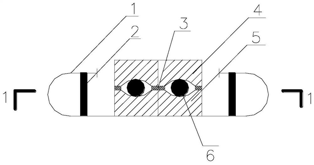
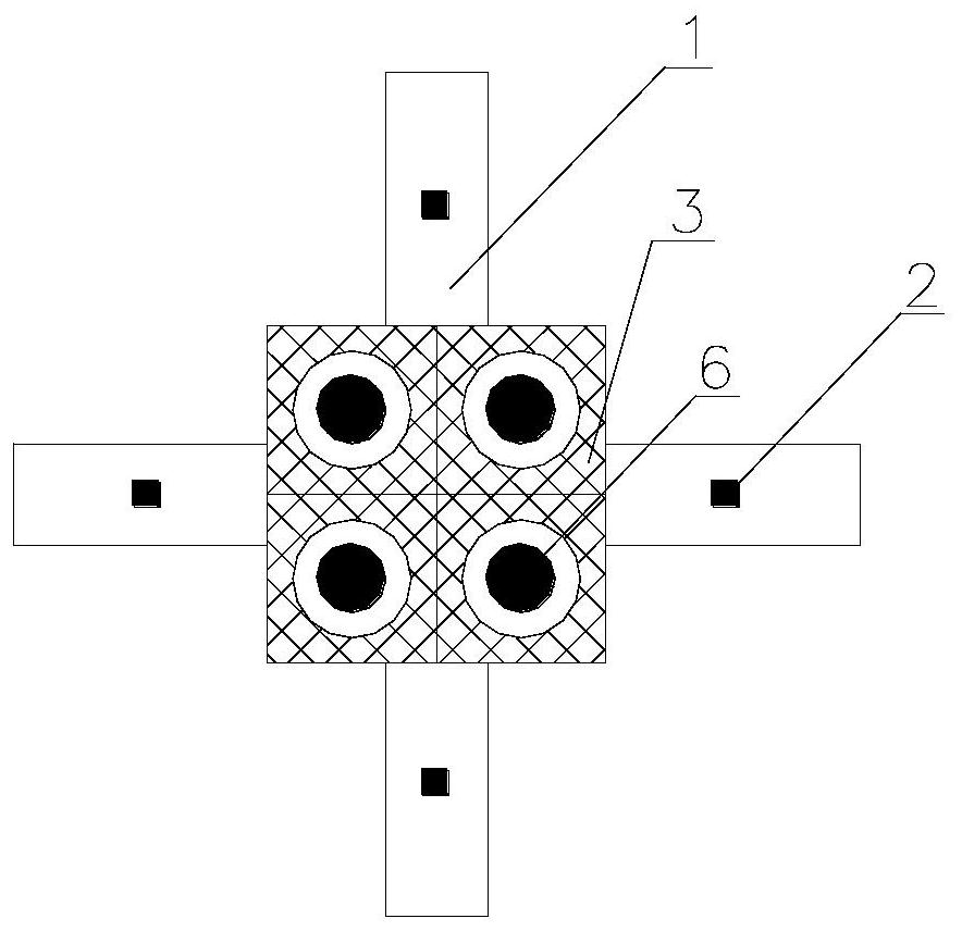
[0019] exist Figure 1 to Figure 2 In the schematic diagram of the present invention shown, the lower rolling groove 5 made of steel is placed on the ground, and four steel balls 6 are placed in the grooves thereon. The upper part of the steel lower rolling groove is provided with a steel upper rolling groove 4, the groove at the lower part of the steel upper rolling groove corresponds to the groove position at the upper part of the steel lower rolling groove, and the groove at the lower part of the steel upper rolling groove and The grooves on the upper part of the steel lower rolling are arc grooves with the same curvature. Rubber blocks 3 are placed between the groove at the bottom of the steel upper rolling groove and the groove at the top of the steel lower rolling groove. Four UI stoppers are distributed around the lower part of the steel lower rolling groove. The UI limiters all include U-shaped steel 1 and I-shaped lead rods 2, and the I-shaped lead rods are arranged...


PUM


Abstract

The invention discloses a composite rolling shock isolation device with UI limiters. A lower steel rolling groove is formed in the ground; four steel balls are placed in a groove in the lower steel rolling groove; an upper steel rolling groove is formed in the upper portion of the lower steel rolling groove; a groove in the lower portion of the upper steel rolling groove corresponds to the groove in the upper portion of the lower steel rolling groove in position; and a rubber block is placed between the groove in the lower portion of the upper steel rolling groove and the groove in the upper portion of the lower steel rolling groove. and the four UI limiters are arranged at the lower portion of the steel lower rolling groove. The stability of the device can be improved, the shock absorption and energy dissipation capacity of the device can be improved, the manufacturing cost of the shock insulation device can be reduced, and the device is simple in structure, convenient in material taking, easy to install and construct, low in manufacturing cost and good in shock insulation effect, has an instantaneous reset function, can achieve the purpose of supporting an upper structure, can also achieve the purpose of isolating earthquakes from being input to the upper structure, and reduces the damage of destructive earthquakes to vertical storage tanks.

Description

technical field [0001] The invention relates to the field of petrochemical industry, in particular to a composite rolling vibration isolation device. Background technique [0002] An important facility for storing LNG is the LNG storage tank, and its ability to resist natural disasters such as sudden earthquakes is an important design indicator of the facility. The numerical simulation analysis of the diffusion range under different meteorological conditions after the catastrophic rupture of the LNG storage tank shows that after the catastrophic rupture of a single 16×104m3 LNG storage tank, the maximum distance of the lower limit concentration of the explosion reaches or even exceeds 15km under certain meteorological conditions. Compared with general storage tank facilities, the structure of large LNG storage tanks is significantly different. It is a double-layer structure system. The outer tank is reinforced prestressed concrete, the inner tank is a stainless steel cylindr...

Claims


Application Information

Patent Timeline
Patent Type & Authority Applications(China)
IPC IPC(8): E02D31/08E02D27/38E02D27/14
CPCE02D31/08E02D27/38E02D27/14
Inventor 李想孙建刚孙治国崔利富万成亮张庆高
Owner DALIAN NATIONALITIES UNIVERSITY
Learn More