Eureka AIR delivers breakthrough ideas for toughest innovation challenges, trusted by R&D personnel around the world.

Ferromagnetic resonance temperature measurement method based on field sweeping method

A ferromagnetic resonance and ferromagnetic technology is applied to thermometers, thermometers, and measuring devices that use directly heat-sensitive electric/magnetic elements, which can solve the problem of long measurement time, complex temperature measurement models, and increased measurement and processing complexity. and other problems, to achieve the effect of simple measurement method, high measurement accuracy, fast and easy measurement

Active Publication Date: 2022-01-14
ZHENGZHOU UNIVERSITY OF LIGHT INDUSTRY
View PDF16 Cites 2 Cited by
  • Summary
  • Abstract
  • Description
  • Claims
  • Application Information

AI Technical Summary

Problems solved by technology

[0004] 1. Temperature measurement is based on the temperature dependence of the reciprocal of magnetic susceptibility of ferromagnetic nanoparticles magnetized under a static magnetic field, but the measurement time of this method is long, and it is difficult to meet the application requirements of rapid temperature measurement
[0005] 2. Temperature measurement based on the temperature dependence of the magnetization of ferromagnetic nanoparticles excited by a single-frequency AC magnetic field, but this method needs to measure the higher harmonics of the magnetization response of ferromagnetic nanoparticles, which increases the difficulty of measurement
[0006] 3. Temperature measurement based on the relationship between the homogeneous or even harmonic amplitude and temperature of the magnetization response of ferromagnetic nanoparticles, but the corresponding temperature measurement model is complex, which increases the complexity of measurement and processing

Method used

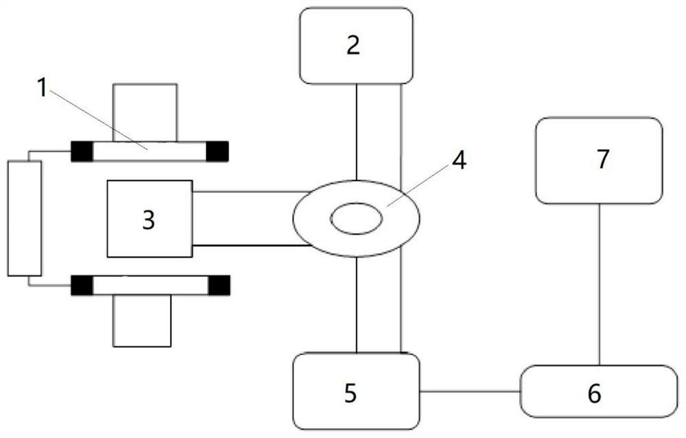
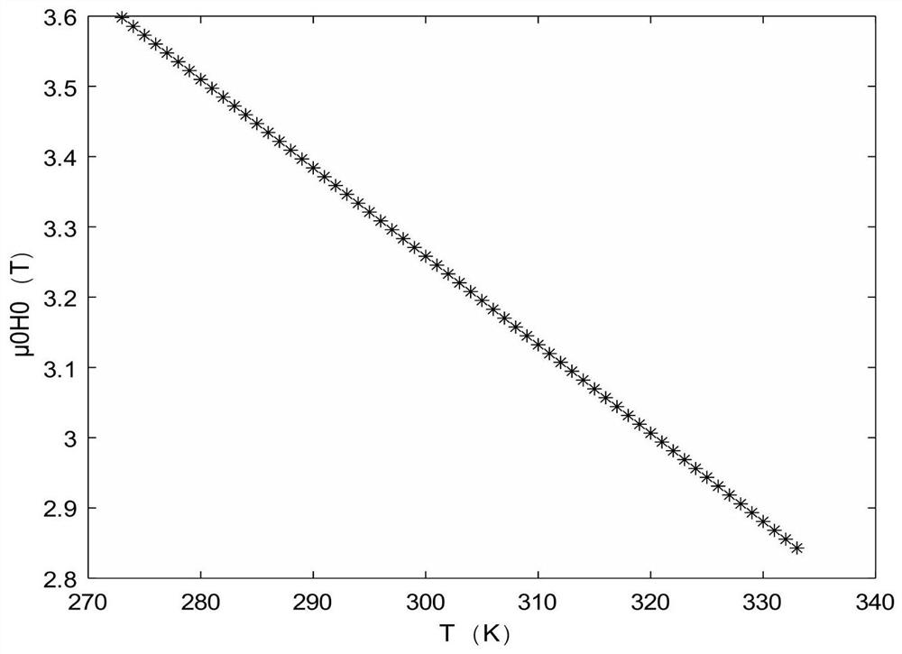

Image

  • Ferromagnetic resonance temperature measurement method based on field sweeping method
  • Ferromagnetic resonance temperature measurement method based on field sweeping method
  • Ferromagnetic resonance temperature measurement method based on field sweeping method

Examples


example

[0045] In order to verify the feasibility of the above-mentioned ferromagnetic resonance temperature measurement method based on the sweeping field method, the inventor designed a simulation experiment according to the content of the invention to repeatedly verify the method. A specific example is used to illustrate:

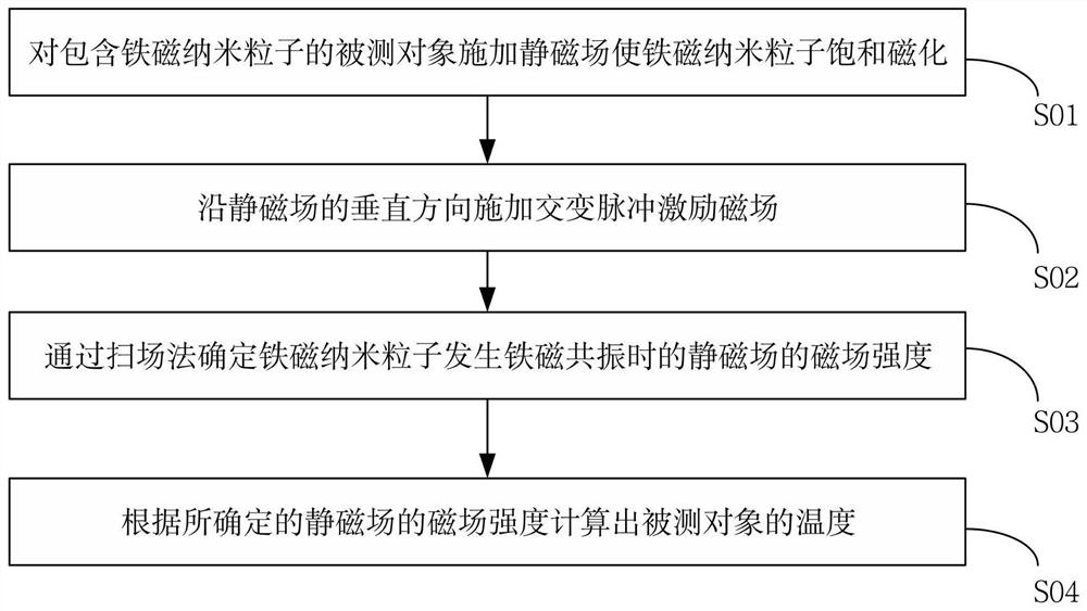
[0046] Add the solution of ferromagnetic nanoparticles into the measured object, put the measured object into the static magnetic field, and perform saturation magnetization on the ferromagnetic nanoparticles;

[0047] A certain amplitude of magnetic induction intensity μ is generated by a microwave source 0 h 1 =10 -4 T microwave pulse excitation, control its frequency f 0 =197GHz, pulse width T p Controlled at 1.5ps, through the microwave circulator, in the direction perpendicular to the static magnetic field, microwave pulse excitation is applied, at f 0 Under the same conditions, change the magnetic field strength H of the static magnetic field 0 The si...


PUM

PropertyMeasurementUnit
particle diameteraaaaaaaaaa

Abstract

The invention relates to a ferromagnetic resonance temperature measurement method based on a field sweeping method. The method comprises the following steps: applying a static magnetic field to a measured object containing ferromagnetic nanoparticles to saturate and magnetize the ferromagnetic nanoparticles; applying an alternating pulse excitation magnetic field along the vertical direction of the static magnetic field; determining the magnetic field intensity of the static magnetic field through a field sweeping method when the ferromagnetic nanoparticles generate ferromagnetic resonance; and calculating the temperature of the measured object according to the determined magnetic field intensity of the static magnetic field. According to the method provided by the invention, temperature measurement is carried out through the established relation model of the magnetic field intensity of the external static magnetic field and the temperature, the model is simple in form, the measurement method is simple and convenient, the internal temperature of the measured object can be rapidly and simply measured, and the measurement accuracy is very high.

Description

technical field [0001] The invention relates to the technical field of temperature measurement, in particular to a temperature measurement method using ferromagnetic nanoparticles. Background technique [0002] Temperature is an important indicator reflecting the internal state of the measured object, and its accurate and fast measurement is very important in many cases. Temperature measurement methods can generally be divided into contact temperature measurement and non-contact temperature measurement. Compared with contact temperature measurement, non-contact temperature measurement can obtain more accurate temperature measurement because it will not destroy the temperature field of the measured object. result. [0003] Due to their unique magnetic properties, ferromagnetic nanoparticles have been used in temperature measurement in many fields and occasions, and because ferromagnetic nanoparticles are nanoscale, they are suitable for non-contact temperature measurement. ...

Claims


Application Information

Patent Timeline
Patent Type & Authority Applications(China)
IPC IPC(8): G01K7/36
CPCG01K7/36
Inventor 苏日建王亚斌杜中州刘文中张秋闻黄臻
Owner ZHENGZHOU UNIVERSITY OF LIGHT INDUSTRY
Why Eureka
Eureka Blog
Learn More