Rapid decontamination equipment for municipal drainage channel
A drainage channel and fast technology, applied in drainage structures, water/sewage treatment, water/sludge/sewage treatment, etc., can solve the problems of time-consuming, labor-intensive and low efficiency of manual cleaning, reduce labor costs and improve cleaning Efficiency and practicability
- Summary
- Abstract
- Description
- Claims
- Application Information
AI Technical Summary
Problems solved by technology
Method used
Image
Examples
Embodiment 1
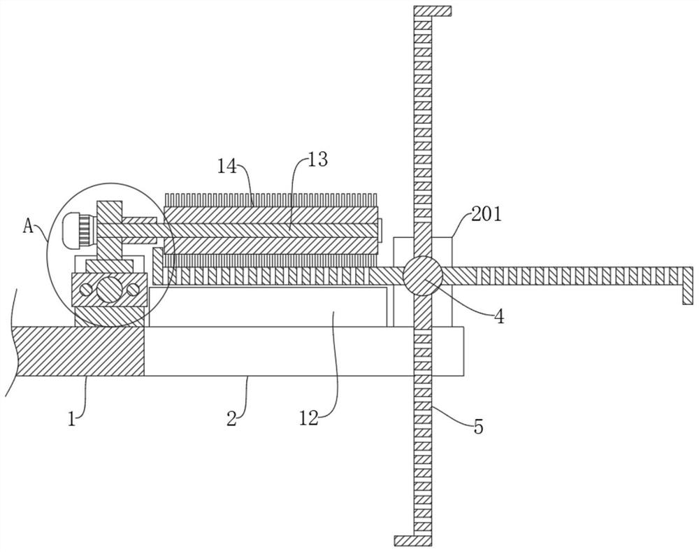
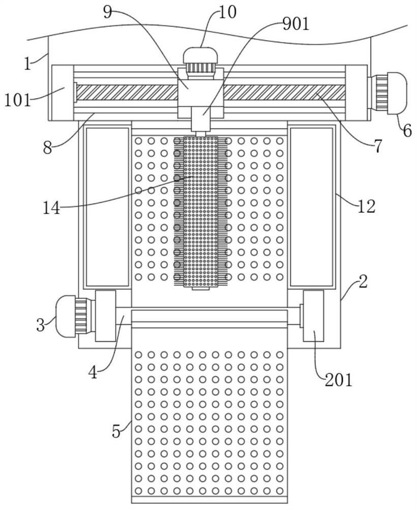
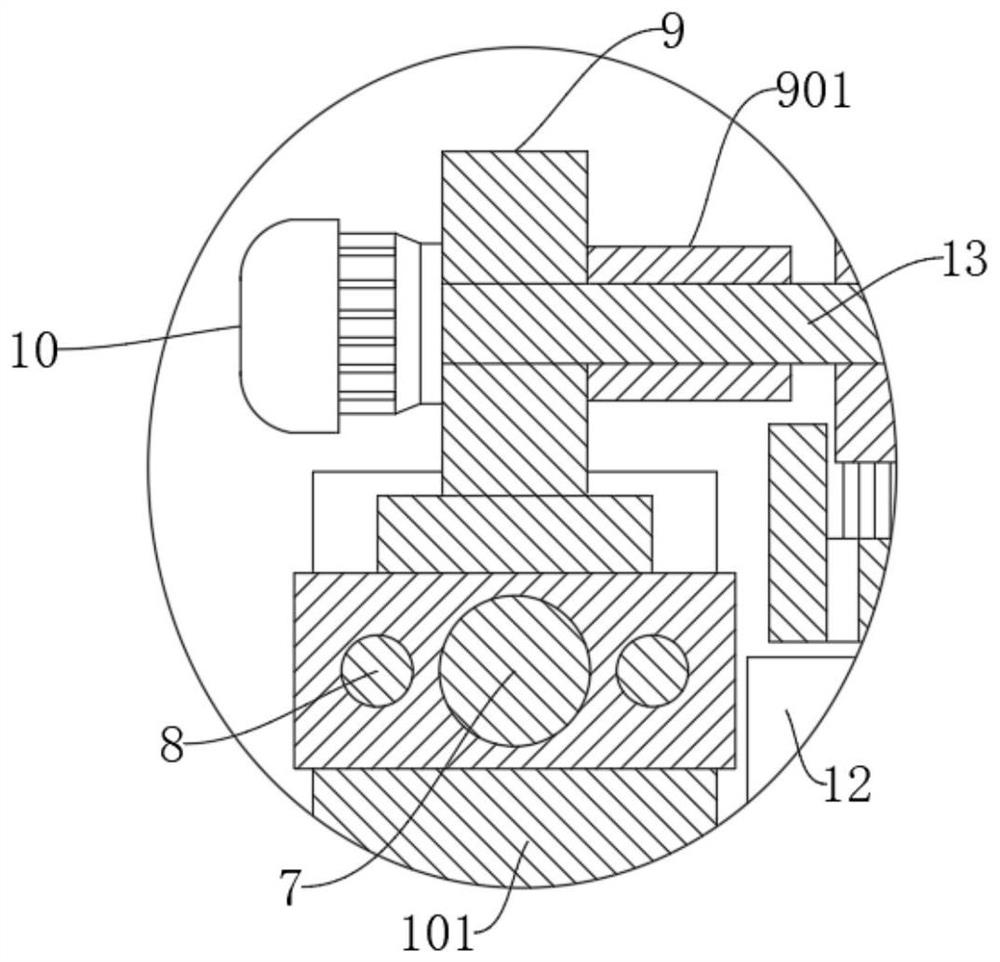
[0023] refer to Figure 1-Figure 3 , a kind of rapid cleaning equipment for municipal drains, including a support plate 1, also includes: a support rod 2, symmetrically fixedly connected to one side of the support plate 1; a first fixed block 201, installed on the support rod 2; a first motor 3. Fixedly connected to any first fixed block 201; the first rotating shaft 4 is rotatably connected to the first fixed block 201, and one end is fixedly connected to the output end of the first motor 3; a plurality of filter plates 5 are evenly distributed on the On the first rotating shaft 4; the concave plate 101 is fixedly connected to the side of the support plate 1 close to the filter plate 5; the second motor 6 is fixedly connected to one end of the concave plate 101; the threaded rod 7 is rotatably connected to the concave plate 101, and one end is fixedly connected to the output end of the second motor 6; the slider is slidably connected to the concave plate 101, and is rotatably...
Embodiment 2
[0026] refer to Figure 1-Figure 3 , a quick cleaning device for municipal drains, which is basically the same as in Embodiment 1, furthermore: the end of the second fixed block 9 away from the third motor 10 is fixedly connected with a support sleeve 901, and the second rotating shaft 13 runs through the support The sleeve 901, through the setting of the supporting sleeve 901, can play a supporting role for the second rotating shaft 13, so that the second rotating shaft 13 can be rotated in a horizontal state, preventing the second rotating shaft 13 from tilting and affecting the cleaning cylinder 14. Cleaning efficiency effectively improves the stability of the second rotating shaft 13;
[0027] The concave plate 101 is fixedly connected to the limit rod 8 near the two sides of the threaded rod 7, and the slider is slidably connected to the limit rod 8. Through the setting of the limit rod 8, the slide block can be moved stably to prevent the slide block from Shaking occurs...
Embodiment 3
[0029] refer to Figure 1-Figure 3 , a quick cleaning device for municipal drains, which is basically the same as that of Embodiment 1, furthermore: the end of the filter plate 5 far away from the first rotating shaft 4 is provided with an anti-drop protrusion, and the filter plate 5 is far away from the first rotating shaft. One end of 4 is provided with an anti-drop protrusion, and when the filter plate 5 drives the sundries to move, it can prevent the sundries from falling back into the drain, thereby improving the efficiency of cleaning the sundries;
[0030] When the filter plate 5 is parallel to the cleaning drum 14, the cleaning brush on the cleaning drum 14 is attached to the surface of the filter plate 5. When the sundries on the filter plate 5 are cleaned, the cleaning efficiency can be improved, and a small amount of sundries can be prevented from remaining on the filter plate 5. After the cleaned filter plate 5 rotates, the sundries can enter the drain again, effec...
PUM
 Abstract
Description
Claims
Application Information
 - R&D
- Intellectual Property
- Life Sciences
- Materials
- Tech Scout
- Unparalleled Data Quality
- Higher Quality Content
- 60% Fewer Hallucinations
Browse by: Latest US Patents, China's latest patents, Technical Efficacy Thesaurus, Application Domain, Technology Topic, Popular Technical Reports.
© 2025 PatSnap. All rights reserved.Legal|Privacy policy|Modern Slavery Act Transparency Statement|Sitemap|About US| Contact US: help@patsnap.com


