
Hot melting equipment for forming self-lubricating bearing metal part

A technology of self-lubricating bearings and metal parts, applied in metal processing equipment, machine tools suitable for grinding the edge of workpieces, welding equipment, etc., can solve problems such as hot melt parts burn workers, affect product quality, and cause danger in the splicing process. Achieve the effect of avoiding wasting a lot of time, improving convenience and saving loading time

Active Publication Date: 2022-01-21
江苏立一新材料科技有限公司
View PDF7 Cites 0 Cited by
  • Summary
  • Abstract
  • Description
  • Claims
  • Application Information

AI Technical Summary

Problems solved by technology

[0002] The hot melt machine is an instrument that transfers the heat of the heating plate to the welding surface of the heating element by means of electric heating to melt the surface, then quickly withdraws the heating plate, and fuses, solidifies, and integrates the molten surface of the heating element after heating. In the manufacture of bearing parts, hot-melt metal parts are required. In the prior art, manual welding is generally used or insert injection molding during injection molding or a hot-melt machine is used. After the parts are hot-melted, due to the strong thermal conductivity of the metal, the splicing process after hot-melting the metal is very dangerous, and it is easy to cause the hot-melt parts to burn the staff, and every time the hot-melt operation is performed, it needs to be re- Calibration of hot-melt parts is very time-consuming, and metal hot-melt, due to the expansion of the inner diameter, will cause splicing burrs on the outside of the inner diameter, so the burr treatment after splicing is also very important, which directly affects product quality. In view of this, here is a proposal A hot-melt equipment for forming self-lubricating bearing metal parts to solve the above problems

Method used


Image

  • Hot melting equipment for forming self-lubricating bearing metal part
  • Hot melting equipment for forming self-lubricating bearing metal part
  • Hot melting equipment for forming self-lubricating bearing metal part

Examples


Embodiment Construction

[0023] The following will clearly and completely describe the technical solutions in the embodiments of the present invention with reference to the accompanying drawings in the embodiments of the present invention. Obviously, the described embodiments are only some, not all, embodiments of the present invention.

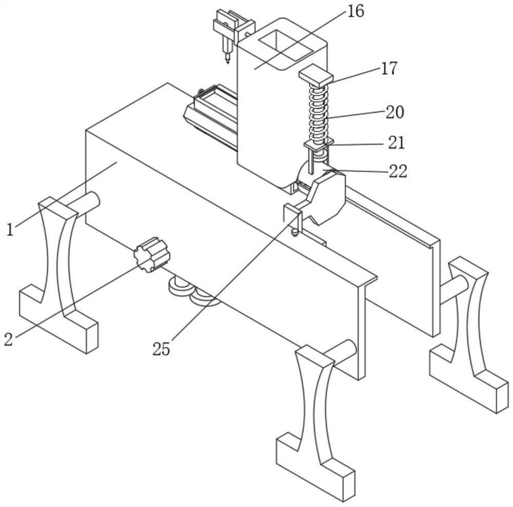
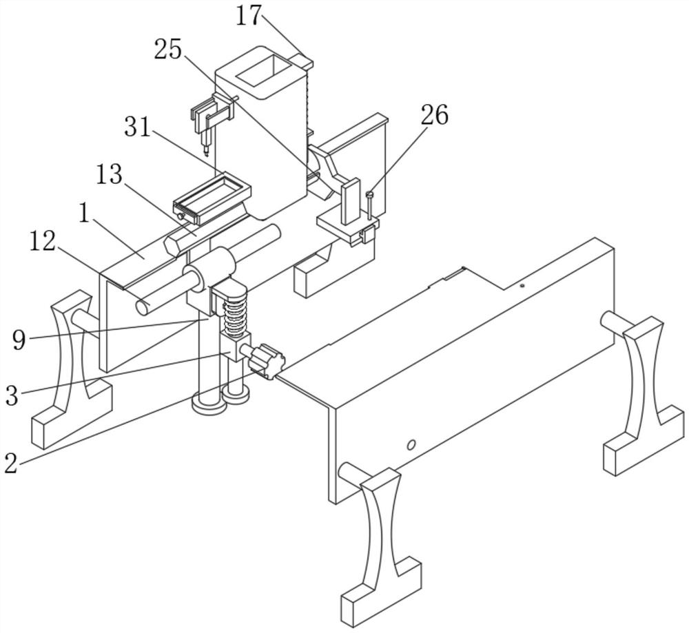
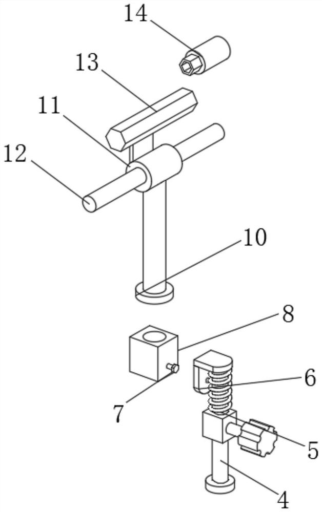
[0024] see figure 1 , figure 2 with image 3 , the present invention provides a technical solution: a hot-melt equipment for forming self-lubricating bearing metal parts, including a carrier 1, a servo motor 2 is fixedly installed on the left side of the front of the carrier 1, and the output shaft of the servo motor 2 is The first driving block 3 is fixedly sleeved, and the middle part of the first driving block 3 is provided with a driving groove. Block 6, a return spring 5 is arranged between the first drive block 3 and the fixed block 6. When the first drive block 3 drives the drive arm 4, the first drive block 3 will squeeze the return spring 5, so that Retu...


PUM


Abstract

The invention discloses hot melting equipment for forming a self-lubricating bearing metal part, and relates to the technical field of bearings, in particular to the hot melting equipment for forming the self-lubricating bearing metal part. The hot melting equipment comprises a bearing frame, and a servo motor is fixedly mounted on the left side of the front surface of the bearing frame; and a first driving block is fixedly connected to an output shaft of the servo motor in a sleeving mode, a driving groove is formed in the middle of the first driving block, a driving arm is movably connected into the driving groove formed in the middle of the first driving block in a sleeving mode, and a fixing block is fixedly installed at the top of the driving arm. According to the hot melting equipment for forming the self-lubricating bearing metal parts, burrs of the hot melting metal parts after hot melting and splicing can be trimmed through a polishing machine, the polishing machine can be effectively operated in different directions through mutual cooperation of a second rotating shaft and a first rotating shaft, burr trimming can be conveniently conducted from different angles, and a containing box can be used for collecting the repaired burrs, so that the working environment is prevented from being stained.

Description

technical field [0001] The invention relates to the technical field of bearings, in particular to a hot-melt equipment for forming metal parts of self-lubricating bearings. Background technique [0002] The hot melt machine is an instrument that transfers the heat of the heating plate to the welding surface of the heating element by means of electric heating to melt the surface, then quickly withdraws the heating plate, and fuses, solidifies, and integrates the molten surface of the heating element after heating. In the manufacture of bearing parts, hot-melt metal parts are required. In the prior art, manual welding is generally used or insert injection molding during injection molding or a hot-melt machine is used. After the parts are hot-melted, due to the strong thermal conductivity of the metal, the splicing process after hot-melting the metal is very dangerous, and it is easy to cause the hot-melt parts to burn the staff, and every time the hot-melt operation is perform...

Claims


Application Information

Patent Timeline
Patent Type & Authority Applications(China)
IPC IPC(8): B23P23/00B23K37/04B23K37/00B24B9/04B24B47/22B24B55/12
CPCB23P23/00B23K37/0426B23K37/00B24B9/04B24B47/22B24B55/12
Inventor 胡安顾媛娟
Owner 江苏立一新材料科技有限公司
Features
  • Generate Ideas
  • Intellectual Property
  • Life Sciences
  • Materials
  • Tech Scout
  • Unparalleled Data Quality
  • Higher Quality Content
  • 60% Fewer Hallucinations
Learn More