Wicker peeling processing equipment for intelligently producing willow products

A technology of processing equipment and willow products, applied in the field of wicker peeling processing equipment, can solve the problems of wicker extrusion damage, transmission mechanism pinching fingers, operator damage, etc., to improve the use effect, reduce the frequency of regular sponge replacement, reduce damage effect

Pending Publication Date: 2022-01-21
ANHUI XINDA HOME FURNISHING CO LTD
View PDF7 Cites 0 Cited by
  • Summary
  • Abstract
  • Description
  • Claims
  • Application Information

AI Technical Summary

Problems solved by technology

[0003] In the process of peeling wicker, the traditional wicker peeling machine needs to manually put the wicker into the transmission mechanism to squeeze and then peel it. Due to the different thickness of the wicker, the rollers on the transmission mechanism are easy to squeeze and damage the wicker. In the wicker process, the operator's hands are easily driven by the wicker and hit the peeling machine, or the fingers are caught by the transmission mechanism, causing damage to the operator

Method used


Image

  • Wicker peeling processing equipment for intelligently producing willow products
  • Wicker peeling processing equipment for intelligently producing willow products
  • Wicker peeling processing equipment for intelligently producing willow products

Examples


Embodiment 1

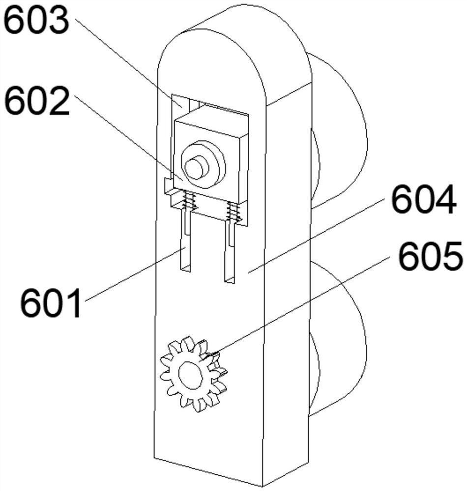
[0031] see figure 2 As shown, the above-mentioned transmission mechanism 6 includes a mounting seat 604 fixedly connected to the support plate 4, and the top of the mounting seat 604 is provided with a mounting groove 603, and both sides of the mounting groove 603 are provided with a slide groove 607, and the mounting groove 603 The bottom of the groove wall is provided with four limiting grooves 601, the interior of the mounting groove 603 is provided with a shock absorbing mechanism 602, the bottom of the mounting seat 604 is provided with a first rotating shaft 606, and one end of the first rotating shaft 606 is fixedly connected with a gear 605, which 605 is transmission-connected with the output end of the drive motor 3 through a chain, and the other end of the first rotating shaft 606 runs through the mounting seat 604 movably.

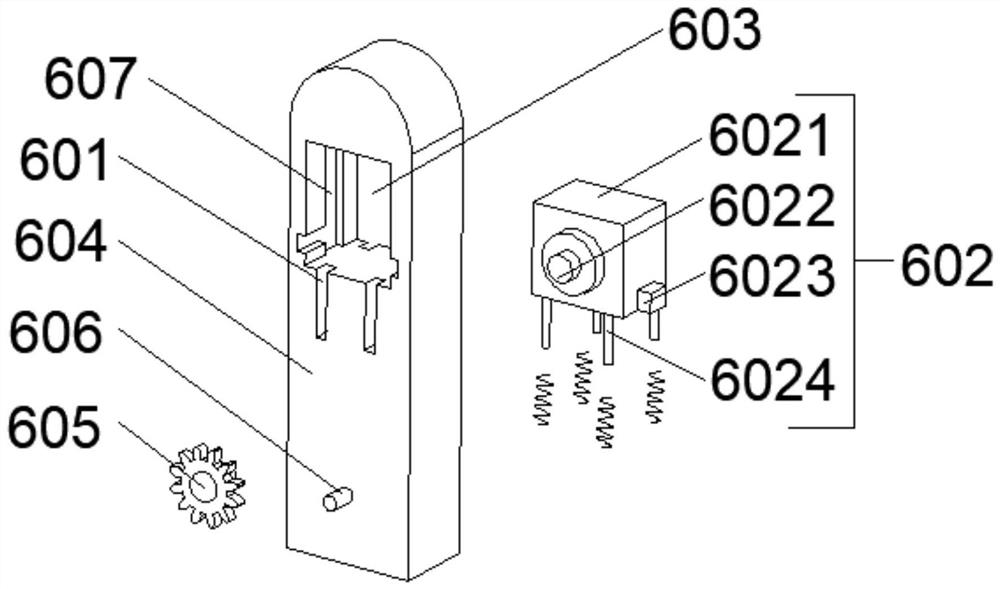
[0032] see image 3 As shown, the above-mentioned cushioning mechanism 602 includes a bearing seat 6021 located in the installation groove 60...

Embodiment 2

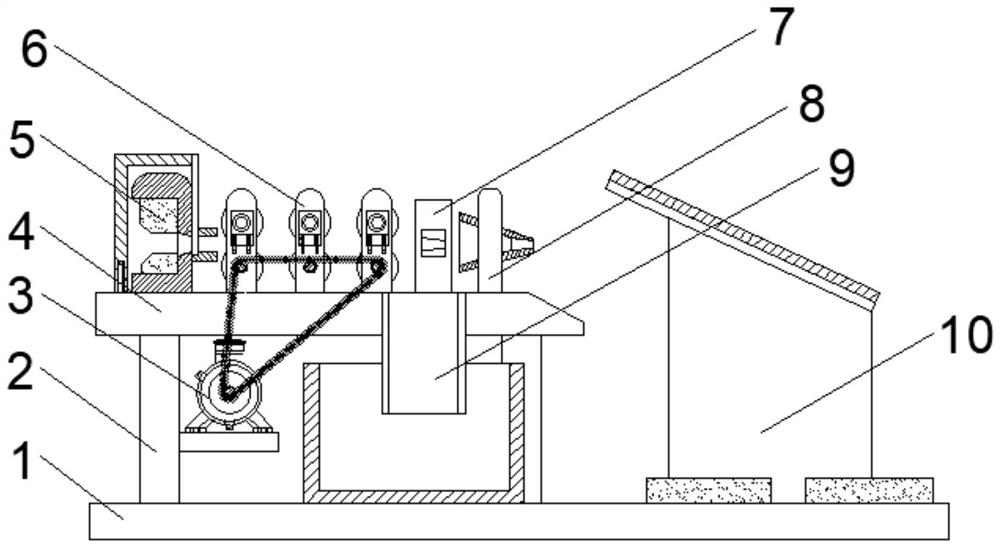
[0035] see Figure 4 with Figure 5As shown, the above-mentioned protection mechanism 5 includes a protection block 501 fixedly connected to the support plate 4. A protection groove is opened on a side of the protection block 501 away from the mounting seat 604. Two sponge pads 505 are arranged inside the protection groove. The protection block 501 There is a through hole facing one side of the mounting base 604, and both sides of the through hole are fixedly connected with the limiting plate 506, the front and rear ends of the mounting base 604 are provided with guide grooves, and the outer side of the protective block 501 is provided with a protective cover 502. The two side inner walls of the protective cover 502 are fixedly connected with the limit strips 507, and the two limit strips 507 are respectively slidably connected with the corresponding guide grooves. The top side of the protective cover 502 is fixedly connected with a shielding plate 504, and the bottom of the s...


PUM


Abstract

The invention relates to wicker peeling processing equipment for intelligently producing willow products. The wicker peeling processing equipment for intelligently producing the willow products comprises a bottom plate; one side of the top of the bottom plate is fixedly provided with a supporting plate through a supporting frame; one side of the top of the supporting plate is provided with a protection mechanism used for preventing hands of an operator from being injured and three transmission mechanisms used for conveying wickers; a driving motor is fixedly installed in the middle of the supporting frame; and a limiting mechanism is arranged on the other side of the top of the bottom plate. The wicker is conveyed through rotation of rollers; tension is provided for a bearing seat through a tension spring, so that the bearing seat provides buffering for a second rotating shaft, and therefore the extrusion effect of the two rollers on the wicker is adjusted, and the wicker can be conveniently and better peeled; and meanwhile, the bearing seat can be conveniently taken down for maintenance and cleaning, the interior of a mounting groove can be effectively cleaned, and the situation that the bearing seat and the mounting groove are blocked is prevented.

Description

technical field [0001] The invention relates to the technical field of willow weaving, in particular to a wicker peeling processing equipment for intelligently producing willow products. Background technique [0002] Willow weaving is one of the traditional folk handicrafts; in ancient times, it was only used as an ordinary daily practical product, and it did not gradually rise until the last few decades of the 20th century, and gradually became an item for export in some areas of China. [0003] In the process of peeling wicker, the traditional wicker peeling machine needs to manually put the wicker into the transmission mechanism to squeeze and then peel it. Due to the different thickness of the wicker, the roller on the transmission mechanism is easy to squeeze and damage the wicker. In the wicker process, the operator's hand is easily driven by the wicker and bumped into the peeling machine, or the fingers are caught by the transmission mechanism, causing damage to the o...

Claims


Application Information

Patent Timeline
Patent Type & Authority Applications(China)
IPC IPC(8): B26D1/02B26D7/02B26D7/06B26D7/22B26D7/27
CPCB26D1/02B26D7/02B26D7/0625B26D7/27B26D7/22
Inventor 李明李东猛
Owner ANHUI XINDA HOME FURNISHING CO LTD
Why Eureka
Try Eureka