Dust-free environment-friendly powder spiral conveying device
A screw conveying device, an environmentally friendly technology, applied in the field of dust-free and environmentally friendly powder screw conveying devices, can solve the problems of polluting the environment, endangering the health of workers, and easy to raise dust, and achieve thin water mist, good dust reduction effect, and avoid The effect of normal use
- Summary
- Abstract
- Description
- Claims
- Application Information
AI Technical Summary
Problems solved by technology
Method used
Image

Examples
Embodiment 1
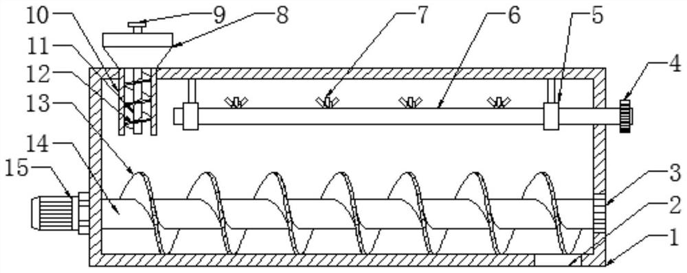
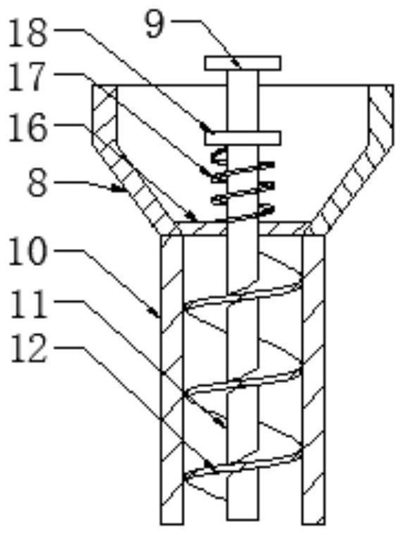
[0021] Embodiment 1 is basically as attached figure 1 Shown: a dust-free and environmentally friendly powder screw conveying device, including a dust suppression mechanism, a conveying cylinder 1 and a screw shaft. One end of the conveying cylinder 1 is provided with a material inlet, and the other end is provided with a discharge port 2. The screw shaft includes a rotating shaft 14 and the helical blade 13 wound around the outer wall of the rotating shaft 14, the two ends of the rotating shaft 14 run through the two ends of the delivery cylinder 1 and are respectively connected with a motor 15 and a rotary joint 3, and the rotating shaft 14 is rotationally connected with the delivery cylinder 1 through the rotary joint 3.
[0022] The dust suppression mechanism includes a water pipe 6 and a plurality of spray pipes 7 connected to the water pipe 6. The distance between the spray pipes 7 is 2-2.5m. The number of the spray pipes 7 depends on the length of the water pipe 6 inside ...
Embodiment 2
[0025] Embodiment 2, the difference with embodiment 1 is: as Figure 4 As shown, a plurality of fan heads 20 are connected to the inside of the top of the delivery tube 1, and the fan heads 20 are connected with fan blades 19. Cables connected to the fan heads 20 are buried inside the wall of the delivery tube 1, and the free ends of the cables extend to the conveyor. The outside of the tube 1 is connected to the power supply, and the fan heads 20 and the spray pipes 7 are arranged alternately.
Embodiment 3
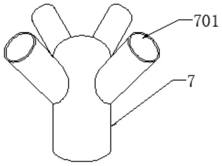
[0026] The difference between embodiment 3 and embodiment 2 is that the spray pipe 7 is a four-way pipe.
[0027] Taking Embodiment 2 as an example, the specific implementation process is as follows: after the water pipe 6 is connected to the water source, the water flows to the spray pipe 7, and under the action of water pressure, the high-pressure atomizing nozzle atomizes the water and sprays it out. The special feature of this solution is that the spray pipe 7 is located on the upper surface of the water pipe 6, and the water outlet 701 of the spray pipe 7 faces upwards. This design makes the sprayed water mist in the spray pipe 7 face upwards first and then under the force of gravity. Under the action, it flows downward again, so that the sprayed water mist flows out in a parabolic shape. This kind of water mist is relatively dispersed, can spray to a larger area, touch more dust, and achieve a good dust reduction effect. Simultaneously, after the fan head 20 is powered ...
PUM
 Abstract
Description
Claims
Application Information
 - R&D
- Intellectual Property
- Life Sciences
- Materials
- Tech Scout
- Unparalleled Data Quality
- Higher Quality Content
- 60% Fewer Hallucinations
Browse by: Latest US Patents, China's latest patents, Technical Efficacy Thesaurus, Application Domain, Technology Topic, Popular Technical Reports.
© 2025 PatSnap. All rights reserved.Legal|Privacy policy|Modern Slavery Act Transparency Statement|Sitemap|About US| Contact US: help@patsnap.com