Bent cap structure adopting a double-main-beam prefabricating and assembling method and construction method thereof

A technology of prefabricated assembly and double main girders, which is applied in the direction of bridges, bridge parts, bridge construction, etc., can solve the problems of mold expansion and deformation of prefabricated shell concrete, complex on-site construction, easy cracking, etc., to achieve fast construction speed and small construction workload , good durability

Pending Publication Date: 2022-01-21
SHANGHAI MUNICIPAL ENG DESIGN INST GRP +1
View PDF13 Cites 4 Cited by
  • Summary
  • Abstract
  • Description
  • Claims
  • Application Information

AI Technical Summary

Problems solved by technology

[0006] CN106638313A provides a large-scale cover beam semi-prefabricated construction technology method, which is improved on the basis of CN 105780663 A, and adopts measures such as installing anti-expansion tie rods in the groove of the prefabricated U-shaped groove and adopting fiber concrete at the bottom of the shell to solve the problem of the first In the process of secondary pouring concrete, there are problems such as mold expansion deformation and prefabricated shell concrete cracking easily
[0010] The existing scheme meets the design and construction requirements of prefabricated assembly, but there are problems with complex on-site construction, which are mainly reflected in three aspects: ① Temporary supports are required to support the prefabricated components; ② The wet joint scheme requires cast-in-place formwork; ③ After Wear prestressed steel beam

Method used


Image

  • Bent cap structure adopting a double-main-beam prefabricating and assembling method and construction method thereof
  • Bent cap structure adopting a double-main-beam prefabricating and assembling method and construction method thereof
  • Bent cap structure adopting a double-main-beam prefabricating and assembling method and construction method thereof

Examples


Embodiment

[0039] Concrete structure and construction method of the present invention are provided in detail by following embodiment and accompanying drawing thereof.

[0040] This embodiment adopts the cover beam structure of double main beam prefabrication and assembly method, as shown in the attached figure 1 ~4, combined with the accompanying drawings, the description is as follows:

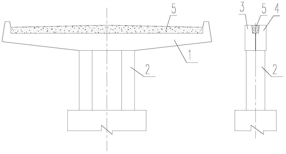
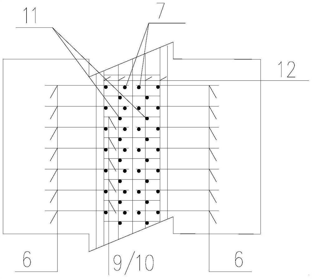
[0041] Such as figure 1 As shown, the cover beam 1 is installed on the top of the pier column 2. The cross section of the cover beam 1 is composed of the left precast section 3, the right precast section 4 and the middle trapezoidal post-cast section 5. The left precast section 3 and the right precast section Section 4 reserves a notch on the upper part, and forms a trapezoidal post-cast section connection structure after assembly.

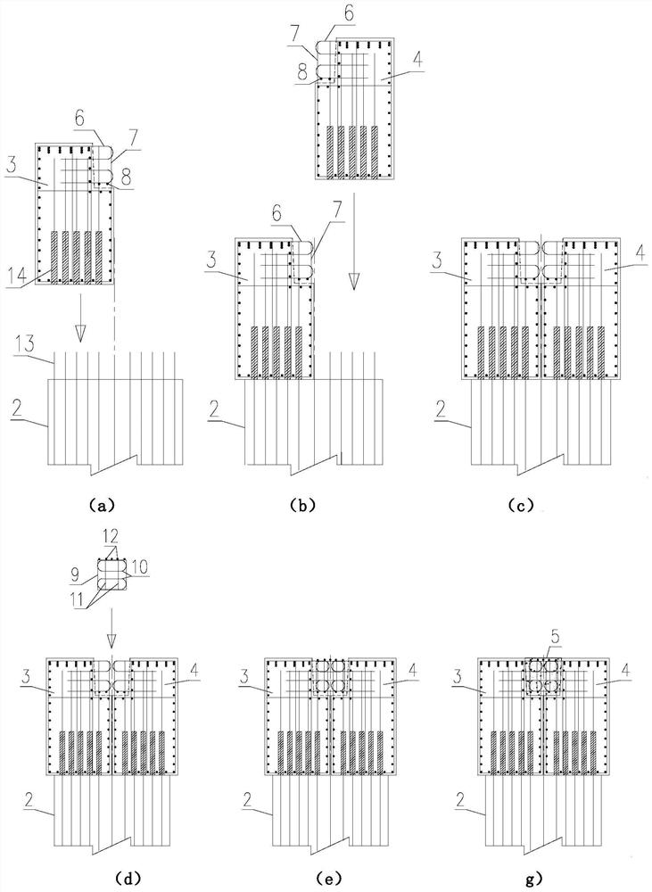
[0042] In this embodiment, the construction steps of the cover beam structure using the double main beam prefabricated assembly method are as follows:

[0043] 1. Prefab...


PUM


Abstract

The invention provides a bent cap structure adopting a double-main-beam prefabricating and assembling method. The cross section of the bent cap is composed of a left prefabricated beam, a right prefabricated beam and a middle trapezoidal post-pouring section, notches are reserved in the upper portions of the two prefabricated sections, and the trapezoidal post-pouring section connecting structure is formed after assembly. According to the construction mode of the trapezoidal post-pouring section located at the top of the bent cap, a post-pouring section reinforcement cage is installed in place at a time, and reserved reinforcements and post-pouring section reinforcements do not need to be connected in a welded mode; the prefabricated section also serves as a formwork, and a post-pouring section formwork does not need to be additionally arranged on site; the prefabricated section is directly hoisted and placed on the top of a pier stand column during installation, and temporary supports or fixing measures are not needed. The bent cap structure has the advantages of being small in site construction workload, high in operability, high in construction speed, good in structural integrity and durability and the like. The bent cap structure is suitable for bent caps which are heavy and need to be transported in a segmented mode.

Description

technical field [0001] The invention belongs to the technical field of bridge prefabrication and assembly, and relates to a cover beam structure, in particular to a cover beam structure using a double main beam prefabrication and assembly method. Background technique [0002] Bridge prefabrication and assembly technology has developed rapidly in recent years. Prefabrication and assembly technology includes factory prefabrication, transportation and hoisting of prefabricated components, and on-site connection technology. The transportation and hoisting of prefabricated components is limited by road transportation along the route and on-site hoisting conditions, so the weight of prefabricated components needs to be controlled. [0003] The viaduct cover girder has the characteristics of concentrated force, large size and heavy weight. As a force-transmitting component between the bridge superstructure and substructure, its structural size is related to the bridge width, span ...

Claims


Application Information

Patent Timeline
Patent Type & Authority Applications(China)
IPC IPC(8): E01D19/00E01D21/00
CPCE01D19/00E01D21/00
Inventor 赵晓梅马骉王浩王巍张培君吴琰
Owner SHANGHAI MUNICIPAL ENG DESIGN INST GRP
Why Eureka
Try Eureka