Anti-blocking double-pneumatic flap valve
A flap valve and anti-clogging technology, which is applied in the field of flap valves, can solve the problems of reducing unloading efficiency, time-consuming and labor-intensive control process, and unfavorable operating efficiency, so as to prevent blockage at the opening, prevent blockage at the opening, and improve operating efficiency. Effect
- Summary
- Abstract
- Description
- Claims
- Application Information
AI Technical Summary
Problems solved by technology
Method used
Image
Examples
Embodiment 1
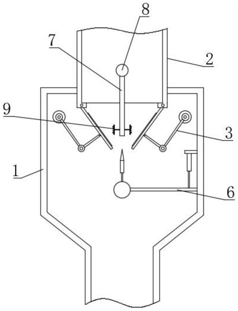
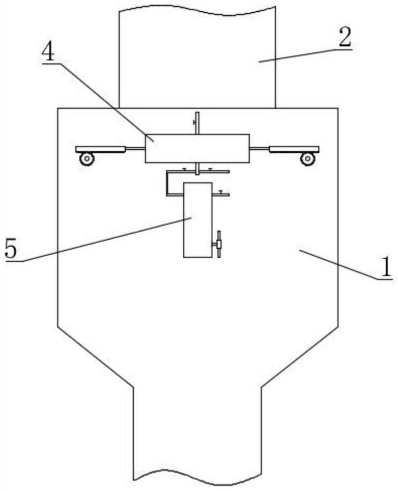
[0046] Such as Figure 1-8 As shown, the double pneumatic flap valve based on anti-clogging proposed by the present invention includes a valve body 1 and a vertical bucket 2. The valve body 1 includes upper and lower layers, and the lower layer structure is the same as the upper layer structure (the lower layer is not drawn in the accompanying drawings) ), the vertical bucket 2 is installed vertically on the top of the valve body 1 and communicates with it, the vertical partition 7 is fixed and installed in the middle of the vertical bucket 2 by bolts, and the top of the vertical partition 7 is equipped with an arc bar 8, the arc bar 8 helps prevent materials from accumulating on the top of the vertical partition 7, the bottom of the vertical bucket 2 is installed with a flap assembly 3, and the flap assembly 3 is located in the valve body 1; the first anti-blocking assembly 6 is installed in the valve body 1 , the second anti-blocking assembly 9 is installed near the bottom o...
Embodiment 2
[0052] Such as Figure 4 , Figure 5 , Figure 9 with Figure 10 As shown, the difference between this embodiment and Embodiment 1 is that the outer wall of the valve body 1 is fixed with a manual control assembly 5 through bolts, and the manual control assembly 5 includes a vertical rectangular block 501, and a vertical rectangular block 501 is provided inside the vertical rectangular block 501. Straight rectangular cavity 509, vertical rectangular block 501 is equipped with air delivery pipe 502 and air extraction pipe 503 near the top position, the other end of air delivery pipe 502 communicates with main pipe 408, the other end of air extraction pipe 503 communicates with the outside world, and air delivery pipe 502 and All valves are installed on the exhaust pipe 503; the second rectangular piston 504 is slidably installed in the vertical rectangular cavity 509, and the bottom of the second rectangular piston 504 is equipped with a threaded sleeve 505 with the opening f...
Embodiment 3
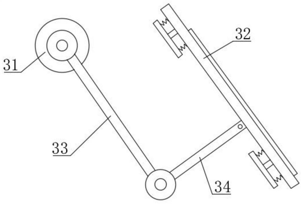
[0055] Such as image 3 with Figure 11 As shown, the difference between this embodiment and Embodiment 1 and Embodiment 2 is that a buffer groove 322 is provided on the turnover plate 32, a buffer protection plate 321 is provided above the turnover plate 32, and a buffer protection plate 321 is installed in the buffer groove 322. The elastic ball 323 that plate 321 is connected, the number of elastic ball 323 is many groups and is evenly distributed in buffer groove 322, and the bottom of turning plate 32 is provided with movable plate 324, and the side of buffer protection plate 321 facing buffer groove 322 is equipped with pressure Rod 325, and one end of pressure bar 325 away from buffer protection plate 321 is connected with movable plate 324, and the number of movable plate 324 is one or more groups, and the bottom of turnover plate 32 is equipped with first spring 326, and first spring 326 and The movable plate 324 is connected;
[0056] When the material falls downwa...
PUM
 Abstract
Description
Claims
Application Information
 - R&D
- Intellectual Property
- Life Sciences
- Materials
- Tech Scout
- Unparalleled Data Quality
- Higher Quality Content
- 60% Fewer Hallucinations
Browse by: Latest US Patents, China's latest patents, Technical Efficacy Thesaurus, Application Domain, Technology Topic, Popular Technical Reports.
© 2025 PatSnap. All rights reserved.Legal|Privacy policy|Modern Slavery Act Transparency Statement|Sitemap|About US| Contact US: help@patsnap.com


