High-pressure system cabin with good heat dissipation effect

A technology of high-voltage system and heat dissipation effect, which is applied in the cooling/ventilation of substation/switchgear, electrical components, substation/distribution device casing, etc. Problems such as obstruction of air flow in the cabin can improve the air flow in the cabin, avoid corrosion, and improve the effect of heat dissipation and ventilation.

Pending Publication Date: 2022-01-21
贵州长江汽车有限公司
View PDF0 Cites 0 Cited by
  • Summary
  • Abstract
  • Description
  • Claims
  • Application Information

AI Technical Summary

Problems solved by technology

High-voltage components will generate a lot of heat during work, making the surrounding environment temperature higher. If the ambient temperature is not effectively controlled within a reasonable range, high-voltage components will have high-temperature alarms and failures, which will bring safety hazards
In the prior art, a ventilation grill is set on the high-pressure maintenance cabin door, and the high-temperature air in the cabin is taken away by the airflow during the running of the vehicle to reduce the ambient temperature in the cabin. The airflow vortex will be formed inside, which will form a certain obstacle to the air flow in the cabin, and the heat dissipation effect will be poor.
Or lay a cooling pipeline system in each high-voltage electrical component. Although this method can effectively guarantee the working temperature of the high-voltage electrical component, it greatly increases the cost of auto parts and manufacturing costs.

Method used


Image

  • High-pressure system cabin with good heat dissipation effect
  • High-pressure system cabin with good heat dissipation effect
  • High-pressure system cabin with good heat dissipation effect

Examples


Embodiment Construction

[0024] The present invention will be further described below in conjunction with the accompanying drawings and embodiments, but not as a basis for limiting the present invention.

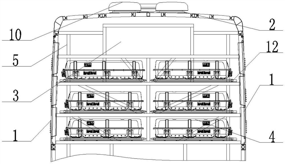
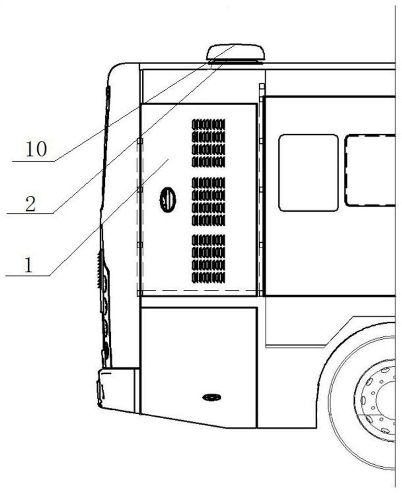
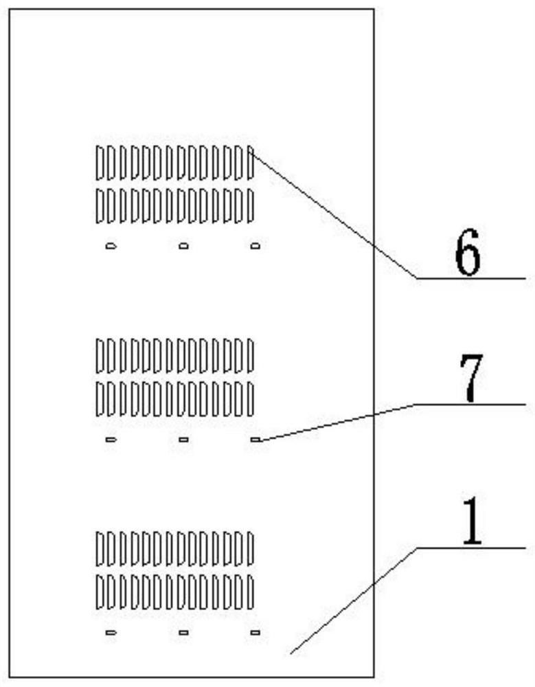
[0025] Embodiment of the present invention: a high-voltage system cabin with good heat dissipation effect, as attached Figure 1-8 As shown, the high-voltage system cabin body 3 is included, and the interior of the high-voltage system cabin body 3 is provided with an electrical component fixing bracket 5, and the electrical component fixing bracket 5 is fixed with a high-voltage electrical component 4 (such as a power battery). A ventilating fan 2 connected to the outside is provided on the top, and a ventilation and waterproof hatch 1 is movably connected to the left and right sides of the high-voltage system cabin body 3, and a plurality of groups of air-induction styles are evenly spaced on the outer wall of the ventilation and waterproof hatch 1. Grille 6, the air intake grille 6 protrudes outwa...


PUM


Abstract

The invention discloses a high-voltage system cabin with a good heat dissipation effect, an electrical apparatus element fixing support is arranged in a high-voltage system cabin body, a high-voltage electrical apparatus element is fixed on the electrical apparatus element fixing support, and a top plate of the high-voltage system cabin body is provided with a ventilator communicated with the outside. The left side and the right side of the high-pressure system cabin body are each movably connected with a ventilation waterproof cabin door, multiple sets of air inducing grilles are evenly arranged on the outer walls of the ventilation waterproof cabin doors at intervals, the air inducing grilles protrude outwards and are exposed to the surfaces of the ventilation waterproof cabin doors, and the opening direction of the air inducing grilles is the same as the advancing direction of a vehicle. A waterproof box protruding inwards is arranged on the back of the ventilation waterproof cabin door provided with the air inducing grille and completely covers the air inducing grille, ventilation holes are densely distributed in a shell of the waterproof box, and a drainage hole communicated with the external environment is formed in the connecting position of the ventilation waterproof cabin door and the bottom of the waterproof box. The LED lamp is simple in structure, good in heat dissipation effect, low in cost and convenient to assemble and disassemble, and well overcomes the defects in the prior art.

Description

technical field [0001] The invention relates to a high-voltage system cabin structure, in particular to a high-pressure system cabin with good heat dissipation effect. Background technique [0002] At present, new energy buses have a variety of high-voltage electrical components with different functions. In general, in order to facilitate installation, layout and management, and to avoid the risk of high-voltage electric shock, high-voltage electrical components are concentrated in the rear area of ​​the vehicle. High-voltage components will generate a lot of heat during the working process, making the surrounding environment temperature higher. If the ambient temperature is not effectively controlled within a reasonable range, high-voltage components will have high-temperature alarms and failures, which will bring safety hazards. In the prior art, a ventilation grill is set on the high-pressure maintenance cabin door, and the high-temperature air in the cabin is taken away...

Claims


Application Information

Patent Timeline
Patent Type & Authority Applications(China)
IPC IPC(8): H02B1/56H02B1/28H02B1/26H02B1/01B60R16/02
CPCH02B1/565H02B1/28H02B1/26H02B1/01B60R16/02
Inventor 王成祥张威
Owner 贵州长江汽车有限公司
Why Eureka
Try Eureka