Cable erecting structure of angle steel tower and installation method of cable erecting structure

A technology of angle steel towers and cables, which is applied in the direction of overhead lines/cable equipment, etc., can solve the problems of downward bending of the middle section of the cable, falling off of the clamping, and large demand for pulling force, so as to improve clamping stability, prevent falling off, and withstand even force effect

Pending Publication Date: 2022-01-21
新昌县银邦电力科技有限公司
View PDF0 Cites 2 Cited by
  • Summary
  • Abstract
  • Description
  • Claims
  • Application Information

AI Technical Summary

Problems solved by technology

[0003] In the process of cable erection at high altitude, the cables need to be laid in parallel, but as the cable laying distance is longer, the gravity of the cable is greater. Under the action of gravity, the middle section of the cable is very easy to cause downward bending
[0004] Most of the existing stretching methods use pulling force, but the demand for stretching force is relatively large, and it is extremely inconvenient to apply force at high altitude, and when the force is applied, due to the large force, it is very easy to cause damage to the outer wall of the clamping end of the cable or Clamping off
[0005] To this end, a cable erection structure of an angle steel tower and its installation method are provided to solve the straightening problem of cables erected at high altitude

Method used


Image

  • Cable erecting structure of angle steel tower and installation method of cable erecting structure
  • Cable erecting structure of angle steel tower and installation method of cable erecting structure
  • Cable erecting structure of angle steel tower and installation method of cable erecting structure

Examples


Embodiment Construction

[0030] The following will clearly and completely describe the technical solutions in the embodiments of the present invention with reference to the accompanying drawings in the embodiments of the present invention. Obviously, the described embodiments are only some, not all, embodiments of the present invention. Based on the embodiments of the present invention, all other embodiments obtained by persons of ordinary skill in the art without making creative efforts belong to the protection scope of the present invention.

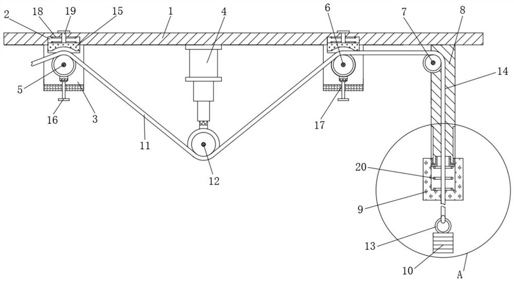
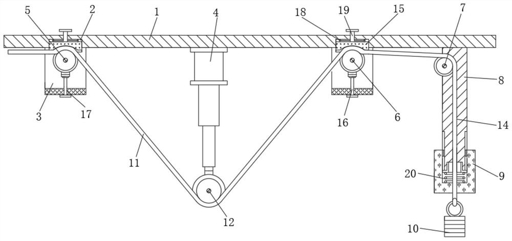
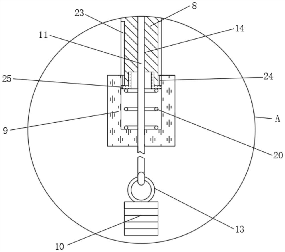
[0031] see Figure 1 to Figure 4 , the present invention provides a technical solution:

[0032] A cable erection structure for an angle steel tower, comprising a beam 1, a pair of symmetrical lower limit frames 3 are arranged at the lower end of the beam 1, and a first Limit wheel 5 and the second limit wheel 6, gap is left between the first limit wheel 5 and the lifting block 15, the lower end of the first limit wheel 5 is provided with a support, and the l...


PUM


Abstract

The invention relates to the technical field of high-altitude cable erection, in particular to a cable erecting structure of an angle steel tower and an installation method of the cable erecting structure. The cable erecting structure comprises a cross beam, a pair of lower limiting frames in bilateral symmetry are arranged at the lower end of the cross beam, an extrusion wheel driven by an electric telescopic rod is vertically and downwards arranged in the middle of the lower end of the cross beam and a stand column is vertically welded to the right side of the lower end of the cross beam. The cable erecting structure has the beneficial effects that a limiting wheel and a lifting block which are driven by an extrusion screw rod are arranged to be matched, so that a cable is extruded and fixed, meanwhile, the cable is bent and staggered at the extrusion position by utilizing an arc-shaped extrusion groove, the clamping stability is further improved, and the cable is prevented from falling off; and through the arrangement of the stand column and a balancing weight with the adjustable gravity, the stress at the two ends of the cable is balanced when force is applied for straightening, the situation that the cable inclines towards one side due to uneven stress is avoided, therefore, under the action of the electric telescopic rod, constant-speed straightening is achieved, the cable is evenly stressed, and protection on the outer wall of the cable is greatly improved.

Description

technical field [0001] The invention relates to the technical field of high-altitude cable erection, in particular to a cable erection structure of an angle steel tower and an installation method thereof. Background technique [0002] Cables are usually installed on adjacent angle steel towers during erection, and in order to reduce the impact of cables on the environment, angle steel frames are usually set higher, so cable erection is a high-altitude operation. [0003] During the high-altitude erection of cables, the cables need to be laid in parallel, but the longer the cable laying distance, the greater the gravity of the cable. Under the action of gravity, the middle section of the cable is easily bent downward. [0004] Most of the existing straightening methods adopt the pulling method of pulling force, but the demand for straightening force is large, and it is extremely inconvenient to apply force at high altitude, and when the force is applied, due to the large forc...

Claims


Application Information

Patent Timeline
Patent Type & Authority Applications(China)
IPC IPC(8): H02G1/04
CPCH02G1/04
Inventor 黄斌
Owner 新昌县银邦电力科技有限公司
Why Eureka
Try Eureka