
Method for producing cylinder crankcase and cylinder crankcase

A technology for crankcases and cylinders, which is applied in the field of producing cylinders and crankcases with foreign matter enclosed, which can solve problems such as high cleaning costs

Pending Publication Date: 2022-01-25
DEUTZ AG
View PDF2 Cites 0 Cited by
  • Summary
  • Abstract
  • Description
  • Claims
  • Application Information

AI Technical Summary

Problems solved by technology

Construction structures with a central frame core have the disadvantage that the area forming the central frame core is very fine
High cleaning costs are required to make the area clean

Method used


Image

  • Method for producing cylinder crankcase and cylinder crankcase
  • Method for producing cylinder crankcase and cylinder crankcase
  • Method for producing cylinder crankcase and cylinder crankcase

Examples


Embodiment Construction

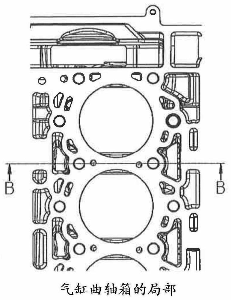
[0013] figure 1 shows a detail of a cylinder crankcase of an internal combustion engine, in particular a diesel internal combustion engine.

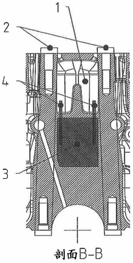
[0014] figure 2 public figure 1 A cross-sectional view of the internal combustion engine along the line B-B. The water jacket 1 between the tension anchors 2 is separated from the tension anchor core 3 by the cast material of the cylinder crankcase of the internal combustion engine. Like the tension anchor core 3 , the pin 4 driven into the tension anchor core 3 is also surrounded by the cast material of the cylinder crankcase of the internal combustion engine, so that no contamination of the core material occurs during subsequent motor operation.

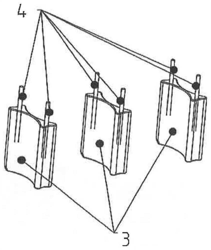
[0015] image 3 The pin 4 driven into the tension anchor core 3 is shown in .

[0016] Figure 4 Showing the water jacket core 5 and image 3 Tension anchor core 3 to be installed in .

[0017] The following solution is shown in the present invention: from figure 2 Below the middle...


PUM


Abstract

The invention relates to and describes a method for generating a cylinder crankcase including a foreign object inclusion for cast reduction and for the improved cleanliness of the generated component. The cast material is in particular removed or pushed from the areas between the tie-rods below the water jacket, to avoid dirt input into the component during later engine operation. The areas below the water jacket between the tie-rods are designed as a separate tie-rod core, and the bolts used during later installation at the water jacket core are enclosed in the tie-rod core, so that the tie-rod core is completely surrounded by cast material in the component following the cast and the bolt has coalesced with the cast, and the tie-rod core remains in the generated component and is located in an encapsulated space generated by the cast material.

Description

technical field [0001] The invention relates to a method for producing a cylinder crankcase with foreign body inclusions. Furthermore, the invention relates to a cylinder crankcase with foreign body inclusions for reduced cast material and better component cleanliness. Background technique [0002] WO 2008011863 A1 discloses a method for producing cast components with cast-in pipes. [0003] Furthermore, EP1060047B1 discloses a method for producing a blank of a cylinder liner to be cast into a light metal crankcase of a reciprocating engine. [0004] In the development of the cylinder crankcase great emphasis was placed on the weight and cleanliness of the components. In today's constructions, it is common for cast material to build up in the area below the water jacket of the cylinder crankcase in the area between the tension anchors of the threaded connection of the main bearing. Alternatively, today's constructions have a center frame core in order to remove material f...

Claims


Application Information

Patent Timeline
Patent Type & Authority Applications(China)
IPC IPC(8): B22C9/22B22C9/10F02F7/00
CPCB22C9/22B22C9/108F02F7/00F02F2200/06B22D19/0009B22D15/02B22D19/00B22C9/103F02F1/16F02F7/0021F02F7/0095
Inventor J·克洛斯特伯格M·斯莱瓦
Owner DEUTZ AG
Learn More