
Automatic feeding and discharging magnetizing equipment for annular device

A technology of automatic loading and unloading and magnetizing equipment, which is applied to magnetic objects, conveyor control devices, conveyors, etc., and can solve the problems of high workload of employees, high production costs, and easy damage to the appearance of the ring.

Pending Publication Date: 2022-01-25
苏州领略智能科技有限公司
View PDF0 Cites 0 Cited by
  • Summary
  • Abstract
  • Description
  • Claims
  • Application Information

AI Technical Summary

Problems solved by technology

[0002] In precision electronic products, the circulator is an important component. In the processing and production of the circulator product, special front-end processing is required first, so the loose parts need to be re-magnetized later. Since the intermediate parts are bulk materials, they cannot It is suitable for automatic loading and unloading of vibrating discs, so it is usually used to manually put the ring into the magnetizing fixture, and then manually put the magnetizing fixture into the magnetizing machine for magnetization. The magnetic speed is slow, and it is easy to damage the appearance of the circulator, the work intensity of the staff is high, and the production cost is high

Method used


Image

  • Automatic feeding and discharging magnetizing equipment for annular device
  • Automatic feeding and discharging magnetizing equipment for annular device
  • Automatic feeding and discharging magnetizing equipment for annular device

Examples


Embodiment Construction

[0044] The present invention will be described in further detail below in conjunction with the accompanying drawings. It should be noted that the words "front", "rear", "left", "right", "upper" and "lower" used in the following description refer to the directions in the drawings, and the words "inner" and "outer ” refer to directions towards or away from the geometric center of a particular part, respectively.

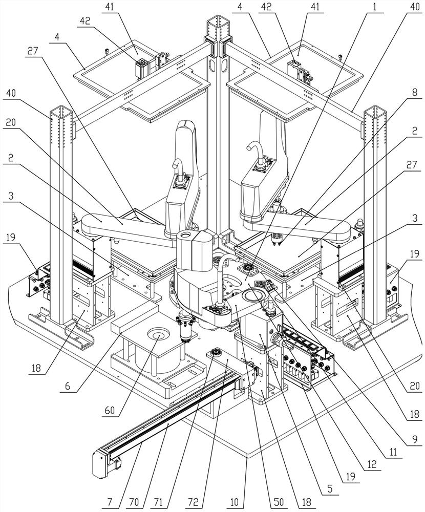
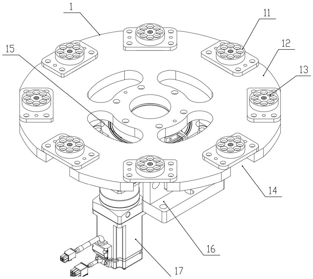
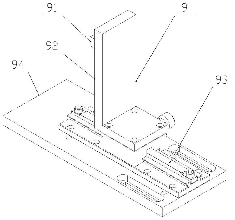
[0045] Figure 1 to Figure 9 It schematically shows an automatic loading and unloading magnetizing device for a circulator according to an embodiment of the present invention. As shown in the figure, the device includes a rotary material transfer part 1 fixed on a base plate 10, two swing material parts 2, two material tables 3, a magnetized material transfer part 5, a magnetizer 6 and a discharge part 7 ;

[0046] Turn the turntable 12 of the material transfer part 1 into a circular array of several wobble jigs 11, and on the wobble jig 11 there are eight storage p...


PUM


Abstract

The invention discloses automatic feeding and discharging magnetizing equipment for an annular device. The automatic feeding and discharging magnetizing equipment comprises a rotary material moving part, two material placing parts, two material tables, a magnetizing material moving part, a magnetizing machine and a discharging part which are fixed to a base panel, multiple disc placing jigs are arranged on a rotary disc of the rotary material moving part in a circumferential array mode, and first mechanical arms of the two material placing parts are located on the upper left portion and the lower right portion of the rotary disc correspondingly; and the two material tables are located on the right side and the rear side of the rotary disc respectively, CCD cameras of two upper visual assemblies are directly connected with high-definition lenses, the high-definition lenses are located over material discs, a second mechanical arm of the magnetizing material moving part is located on the lower left portion of the rotary disc, and the magnetizing machine is located in the middle of the left side of the rotary disc. A single-shaft linear module of the discharging part is transversely arranged and connected to the lower portion of the left end of the base panel. The equipment has the advantages that automatic feeding, discharging and magnetizing are achieved, the working environment of workers is improved, the magnetizing speed is high, the yield of annular devices is high, and the production cost is remarkably reduced.

Description

technical field [0001] The invention relates to automatic magnetization equipment for circulator products, in particular to an automatic loading and unloading magnetization equipment for circulators. Background technique [0002] In precision electronic products, the circulator is an important component. In the processing and production of the circulator product, special front-end processing is required first, so the loose parts need to be re-magnetized later. Since the intermediate parts are bulk materials, they cannot It is suitable for automatic loading and unloading of vibrating discs, so it is usually used to manually put the ring into the magnetizing fixture, and then manually put the magnetizing fixture into the magnetizing machine for magnetization. The magnetic speed is slow, and the appearance of the circulator is easy to be damaged, the work intensity of the employees is high, and the production cost is high. Contents of the invention [0003] In order to solve...

Claims


Application Information

Patent Timeline
IPC IPC(8): B65G43/08B65G47/91H01F13/00
CPCB65G43/08H01F13/003B65G47/914B65G47/917B65G47/918B65G2203/041B65G2203/042B65G2201/02
Inventor 杨康宁彪张晓虎
Owner 苏州领略智能科技有限公司
Learn More