Seeding device with synchronous fertilization function
A technology of seeding device and function, applied in the field of seeding device with synchronous fertilization function, can solve the problems of inconvenience of seeding device, inability to complete fertilization, uneven fertilization, etc., to avoid uneven spreading, simple structure and accurate material use. Effect
- Summary
- Abstract
- Description
- Claims
- Application Information
AI Technical Summary
Problems solved by technology
Method used
Image
Examples
Embodiment 1
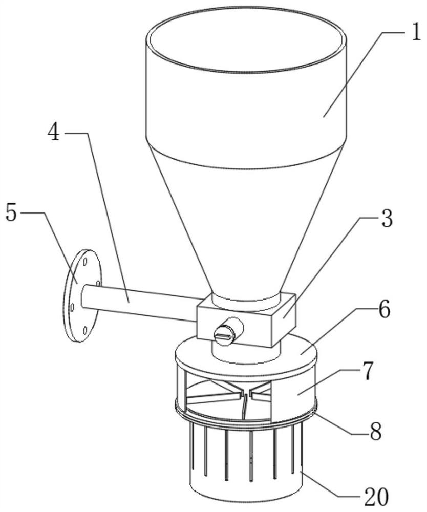
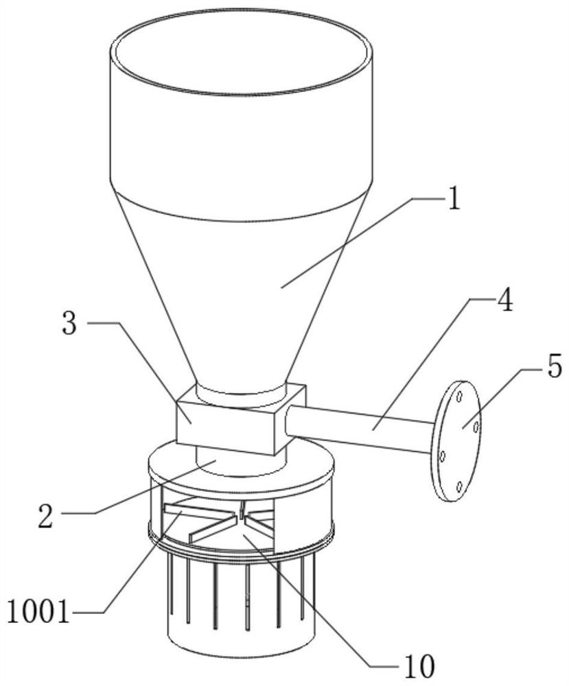
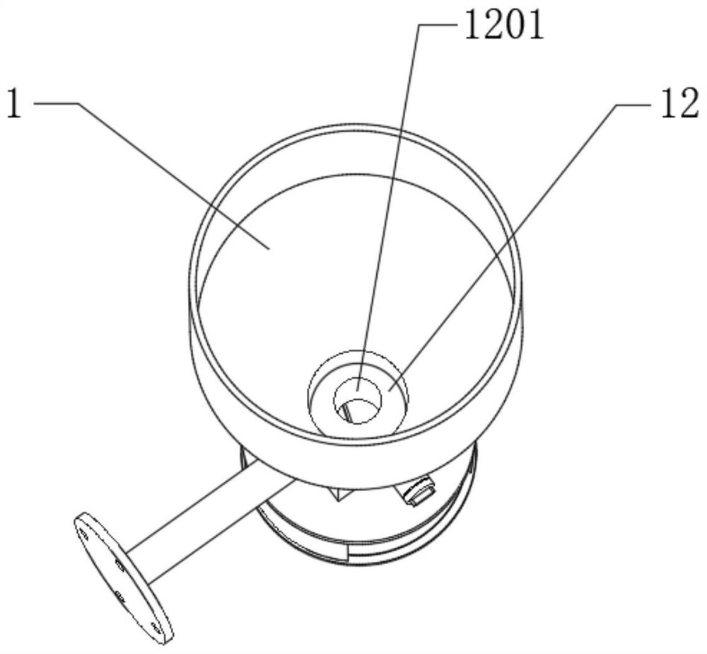
[0031] The embodiment of the invention discloses a seeding device with synchronous fertilization function, such as Figure 1-8 As shown, it includes a fertilizer storage cylinder 1, the bottom of the fertilizer storage cylinder 1 is fixedly connected with a discharge pipe 2, and the middle part of the discharge pipe 2 is fixedly connected with a control box 3, and the inner cavity of the control box 3 is the same as that of the discharge pipe 2 , the side wall of the control box 3 is fixedly connected with a connecting column 4, and the end of the connecting column 4 away from the control box 3 is fixedly connected with an installation circular plate 5, and the bottom of the discharge pipe 2 is fixedly connected with a lower ring plate 6, and the lower ring plate 6 Two groups of arc-shaped baffles 7 are fixedly connected at the bottom of the arc-shaped baffle 7, and the bottom of the arc-shaped baffle 7 is fixedly connected with a bottom circular plate 8, and the bottom center ...
Embodiment 2
[0041] The embodiment of the present invention discloses a seeding device with synchronous fertilization function, such as Figure 1-8 As shown, it includes a fertilizer storage cylinder 1, the bottom of the fertilizer storage cylinder 1 is fixedly connected with a discharge pipe 2, and the middle part of the discharge pipe 2 is fixedly connected with a control box 3, and the inner cavity of the control box 3 is the same as that of the discharge pipe 2 , the side wall of the control box 3 is fixedly connected with a connecting column 4, and the end of the connecting column 4 away from the control box 3 is fixedly connected with an installation circular plate 5, and the bottom of the discharge pipe 2 is fixedly connected with a lower ring plate 6, and the lower ring plate 6 Two groups of arc-shaped baffles 7 are fixedly connected at the bottom of the arc-shaped baffle 7, and the bottom of the arc-shaped baffle 7 is fixedly connected with a bottom circular plate 8, and the bottom...
PUM
 Abstract
Description
Claims
Application Information
 - R&D
- Intellectual Property
- Life Sciences
- Materials
- Tech Scout
- Unparalleled Data Quality
- Higher Quality Content
- 60% Fewer Hallucinations
Browse by: Latest US Patents, China's latest patents, Technical Efficacy Thesaurus, Application Domain, Technology Topic, Popular Technical Reports.
© 2025 PatSnap. All rights reserved.Legal|Privacy policy|Modern Slavery Act Transparency Statement|Sitemap|About US| Contact US: help@patsnap.com


