
Machining device and method for double-thrust sliding bearing in finish machining stage

A technology for sliding bearings and processing devices, which is applied in positioning devices, auxiliary devices, metal processing equipment, etc., and can solve problems such as easy scratches and difficult processing of alloy end faces

Pending Publication Date: 2022-01-28
CSIC NO 12 RES INST
View PDF0 Cites 2 Cited by
  • Summary
  • Abstract
  • Description
  • Claims
  • Application Information

AI Technical Summary

Problems solved by technology

[0005] In order to overcome the above-mentioned existing technical defects, the purpose of the present invention is to provide a processing device and method for double thrust sliding bearings in the finishing stage, which has strong structural integrity, good rigidity, reasonable force, reliable positioning and can eliminate The characteristics of the quality problem that the alloy end face is easy to scratch solve the problem of difficult processing in the prior art

Method used


Image

  • Machining device and method for double-thrust sliding bearing in finish machining stage
  • Machining device and method for double-thrust sliding bearing in finish machining stage
  • Machining device and method for double-thrust sliding bearing in finish machining stage

Examples


Embodiment Construction

[0027] The present invention will be described in detail below with reference to the accompanying drawings and specific embodiments.

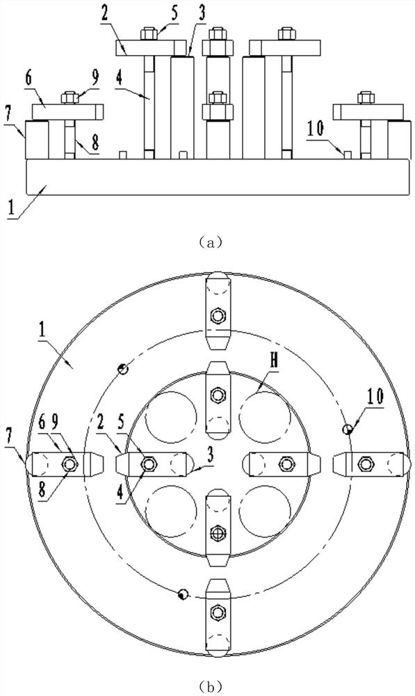
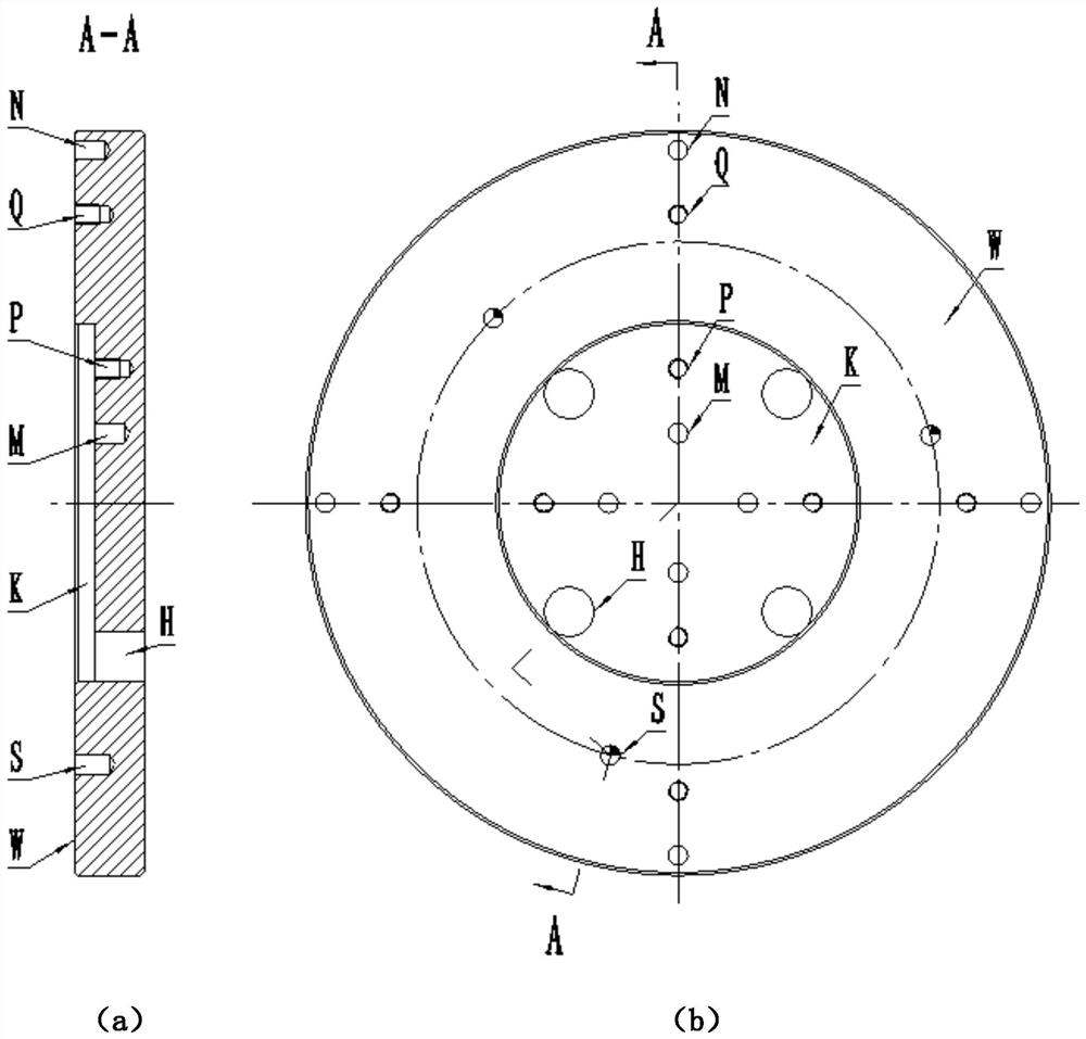
[0028] like figure 1 As shown, a processing device for double-stopping the sliding bearing strip processing stage, including the base 1 and two sets of pressed plates mounted on the base 1;

[0029] The first set of platen is combined with four, and the circumferential direction is formed on the bottom surface K of the base 1, and the axial pressing effect when the bearing is processed, including the pressure plate 2, and the pressure plate 2 is connected by the lock nut 5. The locking screw 4, the inside of the pressure plate 2 is provided with a support rod 3;

[0030] The second set of platen is four, and the circumferential direction is formed on the positioning surface W of the base 1, and the axial pressing effect when the inner hole and the alloy end surface are machined, including B-block 6, B-block 6 through B lock The tightening nut 9 is ...


PUM


Abstract

The invention discloses a machining device and method for a double-thrust sliding bearing in the finish machining stage. The device comprises two sets of pressing plate combinations; a bearing alloy end face F is placed on a base positioning working face to be reliably attached to the base positioning working face; after a bearing is aligned, the first set of pressing plate combination penetrates through an inner hole to tightly press a bearing alloy end face E for finish machining of an outer circle and the second set of pressing plate combination is used for pressing the side face of an outer circular ring groove from the outer portion of the bearing, so that finish machining of an inner hole and an alloy end face E is conducted; then the bearing is turned over, positioning and pressing are conducted through a positioning cylindrical pin and the second set of pressing plate combination, and finish machining of the alloy end face F is conducted. The clamping force layout is reasonable; automatic centering is achieved when the bearing is turned over, and alignment is not needed; the problem that the form and location tolerance cannot meet the design requirement due to the fact that an existing machining device clamps the outer circle of the bearing and the quality problem that a machined alloy end face is prone to being scratched are solved, and the form and location precision and the product quality of a double-thrust sliding bearing are guaranteed.

Description

Technical field [0001] The present invention relates to the field of sliding bearing processing, and Background technique [0002] Double push slip bearing is composed of bimetallic materials (carbon steel and tin-based alloys), the inner holes material and the two end surface materials are made of a tin based alloy. The bearing has two semi-cross-sectional structural features, mounted in the gear case box, used to support the gear shaft to transfer power, but can not only withstand the radial force, but also withstand the two-way axis The role of the force. [0003] Double push sliding bearing is in normal operation, and is injecting a certain pressure in an annular gap between the journal and the bearing aperture and the shoulder end surface and the double-stop bonding end surface. Both "lubricating oil film. When the journal and the bearing aperture and the shoulder end face are in a stable liquid lubrication state, their friction coefficient and wear are minimized, thereby en...

Claims


Application Information

Patent Timeline
IPC IPC(8): B23B1/00B23B5/00B23B25/00B23Q3/12
CPCB23B1/00B23B5/00B23B25/00B23Q3/12
Inventor 周林南飞艳薛飞王大伟张朋李军庆张卫军
Owner CSIC NO 12 RES INST
Learn More