
Metal plate welding device for machining and welding method

A welding device and mechanical processing technology, applied in the field of metal plate welding, can solve the problems of changing the position of the metal plate, affecting the welding result of the metal plate, affecting the welding quality, etc., and achieving the effect of ensuring the welding quality

Active Publication Date: 2022-01-28
安徽润盈建材有限公司
View PDF13 Cites 0 Cited by
  • Summary
  • Abstract
  • Description
  • Claims
  • Application Information

AI Technical Summary

Problems solved by technology

[0002]Metal is a material that is shiny, ductile, and easy to conduct electricity and heat. During the production, processing and use of metal sheets, it is often necessary to Metal sheets are welded to obtain different types of sheets. Most of the existing sheet metal welding is done manually. However, due to factors such as hand collisions during manual welding, it is easy to touch the metal sheets and cause the position of the metal sheets to change, thereby affecting the quality of the metal sheets. Welding results, affecting welding quality

Method used


Image

  • Metal plate welding device for machining and welding method
  • Metal plate welding device for machining and welding method
  • Metal plate welding device for machining and welding method

Examples


Embodiment 1

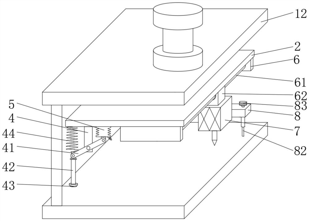
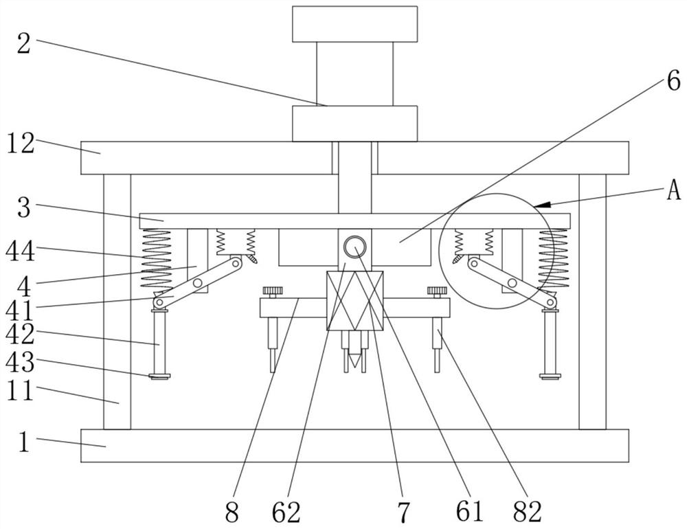
[0031] see Figure 1-2 and Figure 4-5 , the present embodiment provides a metal plate welding device for mechanical processing, comprising a base plate 1, a support column 11 fixedly installed on the upper surface of the base plate 1, and a top plate 12 fixedly installed on the upper end of the support column 11, the lower surface of the installation plate 3 is fixed Front and rear symmetrical risers 6 are installed, threaded rods 61 are installed in rotation between the two risers 6, a motor driving the threaded rods 61 is installed on one of the risers 6, and a moving block 62 is screwed on the threaded rods 61, The lower end of the moving block 62 is fixedly connected with the welding machine 7, and the motor can drive the threaded rod 61 to rotate. When the threaded rod 61 rotates, the moving block 62 can be driven to move along its axial direction, so that the welding machine 7 can be moved along the gap of the metal plate. Move to weld along the gap in the sheet metal....

Embodiment 2

[0039] refer to Figure 1-3 , a further improvement made on the basis of Example 1:

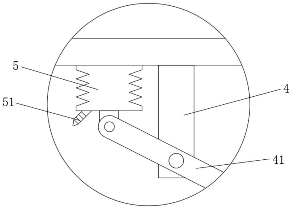
[0040] The upper surface of the top plate 12 is fixedly equipped with the cylinder 2, the output end of the cylinder 2 runs through the top plate 12 and is fixedly connected with the installation plate 3, and the four corners of the lower surface of the installation plate 3 are fixedly installed with the rotating bracket 4, and the lower end of the rotating bracket 4 is rotated and installed. There is a rotating rod 41, one end of the rotating rod 41 is rotatably mounted with a lower pressing rod 42, and the lower end of the lower pressing rod 42 is fixedly connected with a pressing plate 43.

[0041] When the mounting plate 3 moved downwards, the pressing plate 43 at the lower end of the lower pressing rod 42 was in contact with the upper surface of the metal plate, and as the mounting plate 3 continued to move downward, the upper end of the lower pressing rod 42 would push the rotating rod ...


PUM


Abstract

The invention discloses a metal plate welding device for machining and a welding method, which relate to the field of metal plate welding. The metal plate welding device comprises a bottom plate, a supporting column mounted on the upper surface of the bottom plate and a top plate mounted at the upper end of the supporting column, vertical plates are mounted on the lower surface of a mounting plate, and a threaded rod is rotatably mounted between the two vertical plates; a movable block is in threaded connection with the threaded rod, a welding machine is connected to the lower end of the movable block, a rectangular block is connected to the side wall of the welding machine, two symmetrical rectangular sliding grooves are formed in the rectangular block, two sliding blocks are slidably installed in the rectangular sliding grooves correspondingly, and limiting rods are connected to the lower surfaces of the sliding blocks. The rectangular block is arranged on the welding machine, the limiting rods capable of sliding are arranged in the rectangular block, the limiting rods are used for limiting metal plates, the distance between the adjacent limiting rods is adjusted, and it can be guaranteed that a gap between the two metal plates is kept unchanged in the welding process; and the position change caused by touching the metal plate in the welding process is prevented.

Description

technical field [0001] The invention relates to the technical field of metal plate welding, in particular to a metal plate welding device and a welding method for mechanical processing. Background technique [0002] Metal is a substance that is shiny, ductile, and easy to conduct electricity and heat. During the production, processing and use of metal sheets, it is often necessary to weld metal sheets to obtain different types of sheets. The existing Metal sheet welding is mostly done manually, but due to factors such as hand collisions during manual welding, it is easy to touch the metal sheet and cause the position of the metal sheet to change, thereby affecting the welding result of the metal sheet and affecting the welding quality. Contents of the invention [0003] The object of the present invention is to provide a metal plate welding device for mechanical processing to solve the problems raised in the above-mentioned background art. [0004] In order to achieve the...

Claims


Application Information

Patent Timeline
IPC IPC(8): B23K31/02B23K37/02B23K37/04B23K37/00
CPCB23K31/02B23K37/02B23K37/04B23K37/003Y02P70/10
Inventor 王辉王晓敏
Owner 安徽润盈建材有限公司
Learn More